Installation, setup, operation, cont’d, Rear/bottom/side panel features and cabling, Cveq1 series • installation, setup, operation – Extron Electronics CVEQ1, CVEQ1 WM, CVEQ1 AAP User Manual
Page 10
CVEQ1 Series • Installation, Setup, Operation
Installation, Setup, Operation, cont’d
CVEQ1 Series • Installation, Setup, Operation
2-7
Power Connector wiring_compact.eps
Tip (+)
Sleeve
Tip (+)
Sleeve
Power Input
Use a 9 VDC to 24 VDC power supply.
A 12 VDC supply is recommended.
CVEQ1 AAP/CVEQ WM Rear Panel
Power Connector
J2
1
Positive
Negative
N/C
5 mm
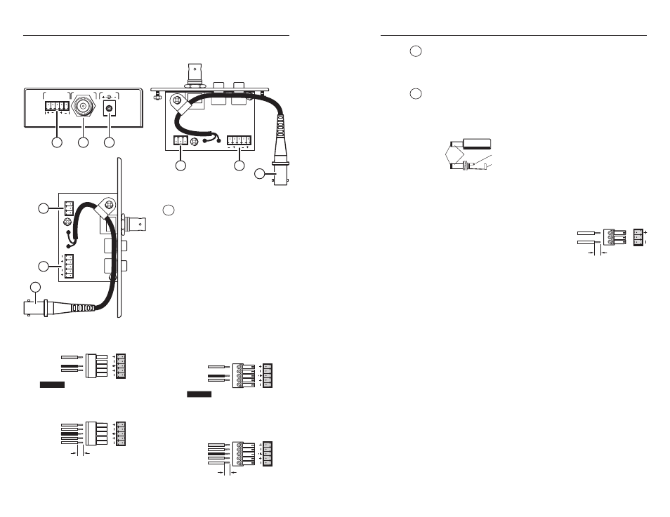
2 Video output connector — Using a coaxial cable, connect
a display device to this female BNC connector. For the
CVEQ1 WM and CVEQ1 AAP, the BNC is at the end of a short
pigtail on the circuit board.
3 Power supply connection — On the CVEQ1 the power input
connector is a 2-pole jack that can be used to connect a 9 VDC
to 24 VDC, 1 A (maximum), external power supply. If you
use an unterminated power supply (Extron parts #70-055-01
or #28-071-02, or #60-357-01 or
#60-432-01), connect the tip of the
jack to the positive (hot) wire, and
the sleeve to the negative/ground
wire, as shown in the illustration at
left.
The CVEQ1 WM and CVEQ1 AAP have a female captive screw
connector instead of a jack for
connecting an external power
source. Wire the power connection
as shown at right.
Rear/Bottom/Side Panel Features and Cabling
1
J6
J2
1
1
J6
J2
1
R
L
R
L
VIDEO OUTPUT
POWER
AUDIO OUTPUT
L
R
R
L
R
L
1
2
3
3
2
1
3
2
1
CVEQ1
Rear Panel
CVEQ1 WM
Side Panel
CVEQ1 AAP
Bottom Panel
1 Audio output connector
— Cable an audio device to
the line driver via this female
5-pole captive screw connector.
Wire the male connector as
shown below.
2-6
CVEQ1
CVEQ1 Unbalanced Audio Output
Tip
See Caution.
Sleeve(s)
Tip
See Caution.
CVEQ1 Balanced Audio Output
Tip
Ring
Sleeve(s)
Tip
Ring
L
R
A
UDIO OUTPUT
A
U
DIO OUTPUT
L
R
CAUTION
Connect the sleeve to ground
(Gnd). Connecting the sleeve to
a negative (–) terminal will
damage the audio output circuits.
Audio Captive Screw Con_
CVEQ1_090605.eps
5 mm
CVEQ1 WM, CVEQ1 AAP
CVEQ1 WM, CVEQ1 AAP
Unbalanced Audio Output
Tip
See Caution.
Sleeve(s)
Tip
See Caution.
CVEQ1 WM, CVEQ1 AAP
Balanced Audio Output
Tip
Ring
Sleeve(s)
Tip
Ring
L
R
A
UDIO OUTPUT
A
U
DIO OUTPUT
L
R
CAUTION
Connect the sleeve to ground
(Gnd). Connecting the sleeve to
a negative (–) terminal will
damage the audio output circuits.
Audio Captive Screw Con_
CVEQ1 WM-AAP_090605.eps
5 mm