Bell & Gossett V58303B Expansion Tanks for Potable Water Systems ASME And Non-Code User Manual
Page 2
MAXIMUM LIMITATIONS
FACTORY
MODEL NUMBER
PRESSURE
TEMPERATURE
PRE-CHARGE
PT-5, PT-12, PT-25V, PT-30V, PT-42V, PT-60V, PT-80V, PT-180V, PT-210V
150 PSIG (1035 kPa)
200°F (93°C)
40 PSIG (379 kPa)
PT-447 through PT-457
150 PSIG (1035 kPa)
240°F (115°C)
55 PSIG (379 kPa)
PTA-5, PTA-12, PTA-20V, PTA-30V, PTA-42V, PTA-60V,PTA-80V, PTA-180V, PTA-210V
150 PSIG (1035 kPa)
200°F (115°C)
55 PSIG (379 kPa)
PTA-447 through PTA-457
125 PSIG (862 kPa)
240°F (115°C)
55 PSIG (379 kPa)
TABLE 1
*Water temperature not to fall below 35°F (1.6°C).
WARNING: State of California Residents.
This product contains a chemical known by the State of
California to cause cancer. This product contains a
chemical known by the State of California to cause birth defects or
other reproductive harm.
WARNING: System fluid under pressure and/or at high
temperatures can be very hazardous. Before servicing,
reduce system pressure to zero or isolate the vessel from
the system. Allow system to cool below 100°F and above 35°F.
Failure to follow this Instruction may result in serious personal injury
and/or property damage.
WARNING: Do not adjust the pressure or re-pressurize
this product except for any adjustments at the time of the
initial installation when the product is new. Only qualified
professionals should check, adjust or re-charge the pre-charge
of tanks. failure to follow this instruction may result in serious per-
sonal injury or death and property damage.
B.
Installation
1.
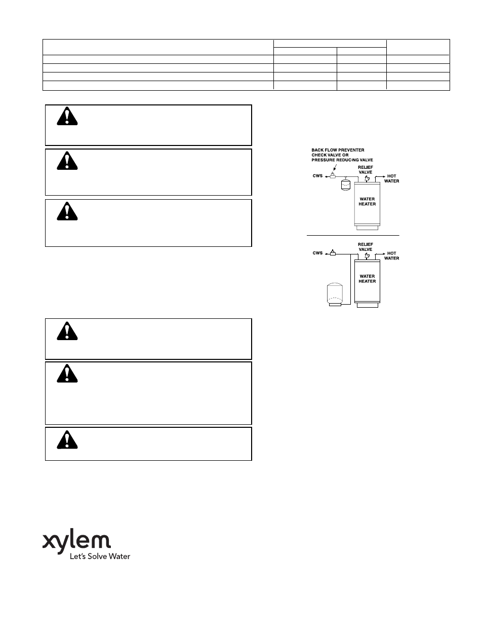
Install the expansion tanks on the cold water supply
(CWS) line at a point between the water heater and back-
flow preventer, check valve or pressure reducing valve
(see Figure 1).
2.
Once tank is installed fill system and check for any leak-
age. Make repairs if necessary.
WARNING: Rupture or Explosion Hazard.
Like most pressurized tanks, this tank can over time cor-
rode, weaken, and burst or explode. Failure to follow this
instruction may result in serious personal injury or death and prop-
erty damage.
WARNING: Chlorine & Aggressive Water Warning.
The water quality can significantly influence the life of
your product. You should test for corrosive elements,
acidity, total solids, and other relevant contaminants, including chlo-
rine and treat your water appropriately to insure satisfactory per-
formance and prevent premature failure. Failure to follow this
instruction may result in serious personal injury or death and prop-
erty damage.
WARNING: Install or store where tank will not be
exposed to temperatures below freezing or above rated
working temperature. Do not expose to any type of
weather.
3.
Before the initial firing of the water heater, open a hot
water fixture and draw water until all air is removed from
the system. Turn the water heater temperature control to
desired ending temperature level (see water heater
instructions).
4.
To relieve initial thermal expansion, slightly open a hot
water faucet. Continue until water heater aquastat tem-
perature is satisfied. Once heater is at its operating range,
no further bleeding of expanded water is required.
5.
The system water heater and expansion tank will now be
operational. The expansion tank will absorb pressure
increases caused by thermal expansion to a level well
below the water heater relief valve setting.
OPERATING INSTRUCTIONS
1.
The expansion tank is installed in the supply line between
the backflow preventer and the water heater. Its sealed-in
air pre-charge prevents water from entering the tank until
the system pressure exceeds the pre-charge pressure.
2.
As the water temperature rises, expanded water enters
the expansion tank’s non-corrosive water reservoir. The
pre-charge air chamber absorbs the pressure increase,
keeping system pressures below the relief valve setting.
3.
As hot water is used, the pressure in the air chamber
forces water back into the system until the expansion
tank is empty. At this point, the pressure in the air cham-
ber once again equals the supply pressure.
NOTE:
Models PT-5, PT-12 and PT-25V are IAPMO listed.
Models PT-5 thru PT-210V are listed under ANSI/NSF Std
61 and City of Los Angeles.
Models PTA-5 thru PTA-210V are listed under ANSI/NSF
Std. 61 and City of Los Angeles.
SERIES “PT” OR “PTA”
IN-LINE MOUNT
MODELS
SERIES “PT” OR “PTA”
FLOOR MOUNT
MODELS
Xylem Inc.
8200 N. Austin Avenue
Morton Grove, Illinois 60053
Phone: (847) 966-3700
Fax: (847) 965-8379
www.xyleminc.com/brands/bellgossett
Bell & Gossett is a trademark of Xylem Inc. or one of its subsidiaries.
© 2012 Xylem Inc. V58303B May 2012