Bell & Gossett V1000187C Circuit Setter Plus Calibrated Balance Valves – Lead-Free User Manual
Page 2
Operational Limits
Description
Bell & Gossett Circuit Setter Plus Balance Valves are precision engineered valves used in heating and cooling systems
which function as precise system balancing valves and highly accurate variable orifice flow meters.
Installation Instructions
Circuit Setter Balance Valves are bi-directional valves and can be installed in most attitudes; however, they should be
installed in a position to facilitate the ease of balancing the system.
NPT and sweat style Circuit Setter Balance Valves are equipped with 1/4” NPT plugged drain port. If the drain port is to
be used to drain a riser on the downstream side of a terminal unit, it should be situated on the terminal unit side of the
riser when installing the Circuit Setter.
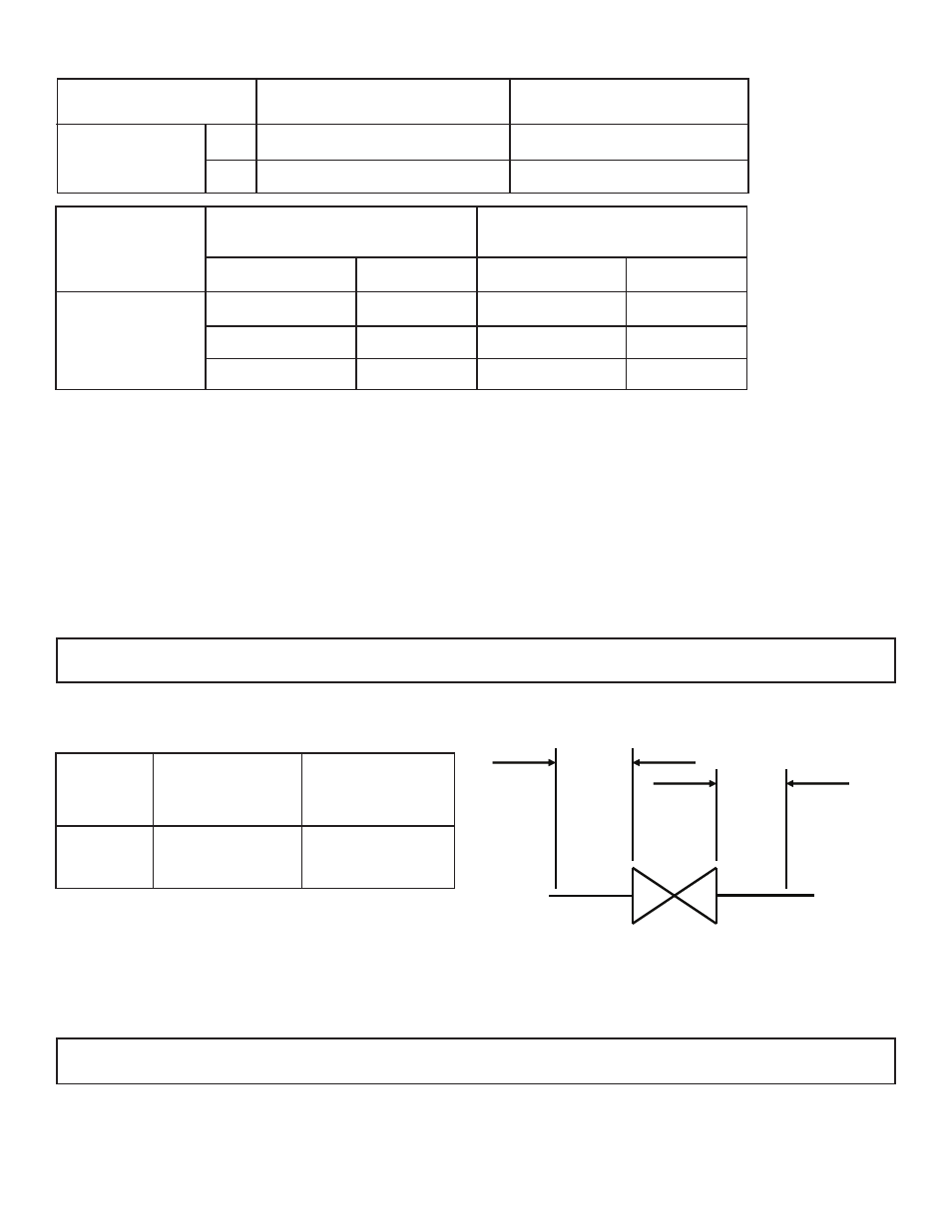
To retain calibrated accuracy, a minimum length of unrestricted straight pipe adjacent to the valve should be
maintained as follows:
Valve
Temperature
Max Working Pressure
Circuit Setter
NPT
-4°F (-20°C) to 250°F (120°C)
400 PSI (2758 kPa)
Sweat Based on Solder Type
ASTM Std. B16.18
Type Solder
Maximum Limitations 1/2” - 1”
Maximum Limitations 1-1/4” - 2”
Pressure PSI (kPa)
Temp °F (°C)
Pressure PSI (kPa)
Temp °F (°C)
300 (2069)
200 (93)
300 (2069)
175 (79)
250 (1724)
225 (107)
250 (1724)
200 (93)
200 (1379)
250 (121)
175 (1207)
250 (121)
95-5
Tin-Antimony
NOTICE: Bell & Gossett Circuit Setter Balance Valves are not recommended for use with meter connections pointing
down. Dirt and debris will collect in the connections and foul up the readout valves and readout meters.
A
B
Size
Upstream ”A”
(In pipe diameter)
Downstream ”B”
(In pipe diameter)
1/2” - 3”
3
1
When installing the Circuit Setter in a coil hook-up kit, the valve should be installed on the return side of the coil with
union end adapter on the upstream side and other end on the downstream side, except when used on the bypass line.
Be aware of water weight in the valve and connected piping when installing your system.
NOTICE: Never use the valve itself as a form of piping support. Please support valves and piping according to the lo-
cal building code. Failure to follow these instructions may result in property damage.
Circuit Setter Balance Valves With Sweat Connections
1. Use a torch with a sharp pointed flame.
2. Clean tube ends and Circuit Setter connections thoroughly.
3. Use 95-5 (Tin-Antimony) solder and a good grade of flux.