Bell & Gossett A85524C Rolairtrol Air Separator User Manual
Rolairtrol, Air separator, Instruction manual
INSTALLER: PLEASE LEAVE THIS MANUAL FOR THE OWNER’S USE.
Rolairtrol
®
Air Separator
SAFETY
INSTRUCTION
This safety alert symbol will be used in this manual to draw attention to safety
related instructions. When used, the safety alert symbol means
ATTENTION!
BECOME ALERT! YOUR SAFETY IS INVOLVED! FAILURE TO FOLLOW
THESE INSTRUCTIONS MAY RESULT IN A SAFETY HAZARD.
DESCRIPTION
The Rolairtrol Air Separator is an ASME vessel designed with tangential open-
ings to create a low velocity vortex where air is separated and removed from the
circulating water. The Rolairtrol is designed and constructed per ASME Section
VIII, Division I. This product is intended for hot and chilled water systems.
OPERATIONAL LIMITS
Maximum Operating Temperature: 350°F
Maximum Operating Pressure: 125 PSIG
INSTALLATION INSTRUCTIONS
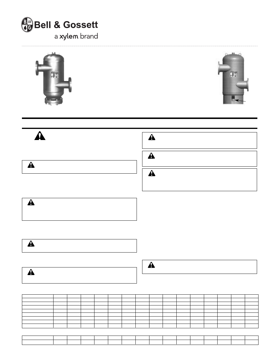
1. Refer to Figures 1 and 2 for the proper installation of the Rolairtrol.
2. Rolairtrol sizes through an “R-8” or “RL-8” can be supported in the piping sys-
tem as long as pipe hangers are attached to the tangential nozzles as close
to the Rolairtrol shell as possible. Sizes larger than an “R-8” or “RL-8” will
need to have additional supports, such as a cradle under the Rolairtrol acting
on a diameter as close to the Rolairtrol outside diameter as possible or factory
installed support brackets.
INSTALLATION INSTRUCTIONS
Note: Welding to the pressure vessel boundary will void the ASME stamp.
3. Model “R” Rolairtrol Air Separators have strainers which must be removed
and cleaned after 24 hours of operation, 30 days of operation and as
required to maintain proper system air separation. Before installing the model
“R” Rolairtrol refer to Table 2 for minimum distances to be maintained
between the blowdown connection or end of the pipe plug and the floor or
other equipment for strainer removal.
4. A manual blowdown valve (MBV-1) can be added to the blowdown connec-
tion. The function of the MBV-1 is to facilitate the purging of sediment from
the vessel.
5. A manual blowdown valve (MBV-1) can be added to the 3" through 12" tanks
of the R models, by removing the 3" pipe plug and replacing with the proper
sized reducer.
2", 2
1
/
2
", 14" THROUGH 24"
R AND RL MODELS
3" THROUGH 12"
R AND RL MODELS
2" PLUG FOR RL
3" PLUG FOR R
WARNING: Carefully read the Instruction Manual to avoid serious
personal injury and property hazards and to ensure safe use and
proper care of this product.
NOT FOR USE IN DOMESTIC (POTABLE) WATER SYSTEMS
DANGER: Rolairtrol Air Separator is for use in closed loop systems
only. Domestic, potable or fresh water can cause serious corrosion in a
tank. This can result in leakage and property damage. Do not use for
domestic, potable or fresh water. Failure to follow this instruction will result
in serious personal injury and property damage.
CAUTION: Hot uninsulated surfaces can cause burns to the skin. Do
not touch hot surfaces. Failure to follow these instructions could
result in moderate personal injury.
CAUTION: Use unit lifting lugs only to lift unit as shipped from
factory. Unit must be empty and disconnected from pipe, and other
restraints. Use proper rigging procedures. Failure to follow these instruc-
tions could result in injury or property damage.
WARNING: Wet weight of Rolairtrols can exceed strength of sup-
ports. Make sure the provisions are made to support the wet weight
and not just the dry weight (see Table 1). Failure to follow these instruc-
tions could result in serious personal injury or death and property damage.
WARNING: This product must be installed by a qualified professional.
Failure to follow the instruction in accompanying manual may cause
a leakage or explosion which may result in serious injury or death and
property damage.
WARNING: The use of improper mating flanges, connectors, gaskets
or bolting can cause flange or connector failure resulting in the loss
of hot or cold system fluid. Use only companion cast iron ANSI flanges or
connectors with appropriate gaskets and properly tightened bolts. Failure
to follow this instruction can result in serious personal injury and/or prop-
erty damage.
WARNING: CALIFORNIA PROPOSITION 65 WARNING!
This product contains a chemical known by the State of California to
cause cancer and to cause birth defects or other reproductive harm.
size (inches)
2
2
1
/
2
3
4
5
6
8
10
12
14
16
18
20
22
24
R vol. (gal)
2
3
7
13
25
34
90
150
291
472
723
1149
1577
1958
2463
R Cv
44
64
119
257
398
632
1020
1789
2665
1445
1885
2340
2945
3725
4325
R dry wt. (lbs)
55
90
130
170
220
295
460
845
1165
1780
2425
3410
5310
6400
7500
R wet wt. (lbs)
70
115
188
278
429
579
1211
2097
3588
5719
8458
12998
18470
22740
28054
RL vol. (gal)
2
3
7
13
25
34
90
150
291
472
723
1149
1577
1958
2463
RL dry wt. (lbs)
50
85
115
155
205
280
420
800
1110
1780
2425
3410
5310
6400
7500
RL wet wt. (lbs)
65
110
173
263
414
564
1171
2052
3538
5719
8458
12998
18470
22740
28054
RL Cv
55
80
215
370
580
850
1445
2340
3300
3900
5100
6410
8000
10000
11700
Cv, APPROXIMATE VOLUME AND WEIGHT (Table 1)
size (inches)
2
2
1
/
2
3
4
5
6
8
10
12
14
16
18
20
22
24
distance
8.5
8.5
12
14
16
19
23
28
31
37
42
52
56
60
64
DISTANCE IN INCHES REQUIRED TO REMOVE STRAINER (Table 2)
INSTRUCTION MANUAL
A85524C