Bell & Gossett S12596B Technologic 350 Pump Controller User Manual
Page 7
7
1.8
FIELD CONNECTION DIAGRAMS
1.8.1
Refer to the pump Installation, Opreation, and mainte-
nance Manual for specific details unique to the pump.
1.8.2
Refer to the flow sensor/transmitter Installation,
Operation, and Maintenance Manual for specific
details unique to the flow sensor/transmitter.
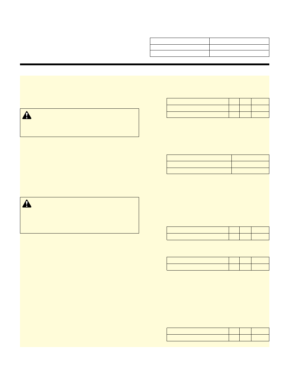
1.8.3
The following field connection diagrams should be
reviewed prior to unit installation and operation.
Drawing #
Description
Job Specific Print(s)
Wiring Diagram(s)
Job Specific Print
Dimensional Drawings
2.0
LOCATION
2.1
Locate the Technologic Controller so that it will be
easily accessible for inspection, maintenance and
service.
2.2
INSTALLATION
This unit is built to give you years of service; install it
properly and provide a suitable foundation. (Check
the shipping ticket for unit weight.) Mount the unit to
provide a rigid connection that will not move or shift
under any circumstance.
2.3
LEVELING
Mount the unit on a level surface and check that it is
plumb on all sides.
2.4
WIRING
2.4.1
POWER WIRING
The Technologic 350 control panel can be set up to
operate across a broad range of voltages. It was fac-
tory set to operate on the voltage shown on the name-
plate. Verify proper transformer primary wiring per the
job-specific wiring diagram. Check power leads in
accordance with wiring diagram enclosed in control
cabinet. The voltage tolerance is +10%/-10%.
2.4.2
ANALOG SIGNAL WIRING
If installing the panel on an existing system, shielded
cable (#22 AWG, Belden type 8762, Alpha #2411 or
equal) should be installed for the DC control wiring.
The shield must be terminated in the Technologic 350
control panel. Do not connect the shield at the other
end of the cable! Insulate the shield so that no electri-
cal connection is made at the other end of the cable.
A twisted pair of #22 AWG conductors (Belden 8442
or equal) can be used in place of shielded cable. The
cable length must be limited to 3000 feet for #22
AWG wire.
2.4.2.1
PRESSURE TRANSMITTER WIRING
(Optional) (4-20mA Analog Signals)
Terminals (J3)
+
-
Shield
1PT Pressure Transmitter
3
2
4
2PT Pressure Transmitter
3
6
4
2.4.2.2
TEMPERATURE SENSOR WIRING
(Optional) (Analog Resistance Input)
The Tech 350 uses resistance temperature detectors
(RTDs) to sense the T-1 and T-2 water temperatures.
These devices change their resistance as the water
temperature changes.
Temperature Sensor (RTD) Wiring
Terminals (J3)
T-1 Low Temperature Sensor
13, 14
T-2 High Temperature Sensor
16, 17
2.4.2.3
FLOW SENSOR/TRANSMITTER WIRING
AND INSTALLATION
(Optional) (4-20mA Analog Signal)
The flow sensor should be installed at an angle no
greater than 45 degrees from top dead center in a
horizontal installation (see Manufacturer’s IOM). See
the Bell & Gossett drawing for installation instructions.
The signal wiring should be terminated in the Tech
350 panel at the terminals below.
Optional Flow Sensor/Transmitter (1FT)
+
-
Shield
Terminals (J3)
9
8
10
2.4.2.4
TEMPERATURE TRANSMITTER WIRING
(Optional) (4-20mA Analog Signal)
Terminal J3
+
-
Shield
AI-4 Temperature Transmitter
9
12
10
2.4.3
DIGITAL SIGNAL WIRING
2.4.3.1
DIFFERENTIAL PRESSURE SWITCH
PIPING AND WIRING
(Optional) (Digital Signal)
Differential pressure switches installed to sense the
increase in pressure between the pump suction and
discharge gauge taps are used to determine whether
a pump is running. Each switch should be wired from
the normally closed contact to the terminals below.
Pump #
1
2
3
Terminal (J4)
9, 8 10, 11
11, 12
SECTION 2 – INSTALLATION
DANGER: Heavy load, may drop if not lifted properly.
Do not lift the entire unit by the motor eyebolts. Lift
the unit with slings placed under the unit base rails.
Failure to follow these instructions could result in seri-
ous personal injury, death, and/or property damage.
DANGER: Electrical shock hazard. Inspect all electri-
cal connections prior to powering the unit. Wiring
connections must be made by a qualified electrician in
accordance with all applicable codes, ordinances, and
good practices.
Failure to follow these instructions
could result in serious personal injury, death, and/or
property damage.