2 connecting the profibus cable, Connecting the profibus cable – YSI IQ SensorNet MIQ/A-PR Module User Manual
Page 12
Interface for the PROFIBUS
MIQ/(A-)PR
12
ba76020e01
01/2012
3.2.2
Connecting the PROFIBUS cable
The MIQ/(A-)PR component can be connected at the PROFIBUS end
(A) or with a loop-through (B).
Fig. 3-4
Connection options of the MIQ/(A-)PR at the PROFIBUS cable,
(A) at the end or (B) with loop-through
(A)
Connecting the
MIQ/(A-)PR component
at the PROFIBUS end
Fig. 3-5
PROFIBUS cable with insulating tape
(A)
(B)
(A)
Instruments connected
to the PROFIBUS,
e.g. MIQ/MC(-A)-PR
PROFIBUS cable
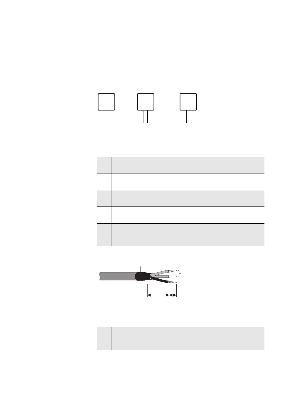
1
Carefully strip the PROFIBUS cable insulation for approx. 20
mm.
2
Bare the PROFIBUS wires from the shielding braid and strip
them for approx. 5 mm.
3
Twist the shielding braid and cover it with approx. 15 mm
insulating tube.
4
Feed the PROFIBUS cable through the cable gland into the
module housing of the MIQ/(A-)PR.
5
Additionally insulate the transition between cable sheath and
insulating tube of the shielding braid (e.g. with insulating tape
or shrinkable tubing), so that no shielding braid is uncovered.
6
Connect the PROFIBUS wires and shield to the terminal
connections of the PROFIBUS module (connections ALine,
BLine and Shield, see section 3.2.1).
L1: approx. 15 mm
L2: approx. 5 mm
L2
L1
Profibus wires
Shield
Insulating tape