3 test and verification procedure – YSI 3200 User Manual
Page 64
Warranty and Repair
Section 9
9.3 TEST AND VERIFICATION PROCEDURE
Connect the YSI Model 3200 as shown in the Test and Verification Figure and follow the charts
below to verify its accuracy.
Equipment Required:
If using the YSI 3166 Precision Calibrator Set to simulate conductance, a YSI 3232 adapter is
required for proper connection to the cell connector. When using the 3232 adapter, temperature
can only be accessed via the EXT. TEMP connector which requires a .25” three conductor phone
plug.
If a decade resistance box is used to simulate conductance and temperature, a YSI #003229 cable
is required for connection to the cell connector.
Important Notes:
1. Temperature compensation must be turned off.
2. Put the 3200 in manual range mode.
3. Set the units to conductance and/or resistance.
4. The 3200 has no internal calibration. Opening the case should only be attempted by a
qualified service technician or permanent damage may result.
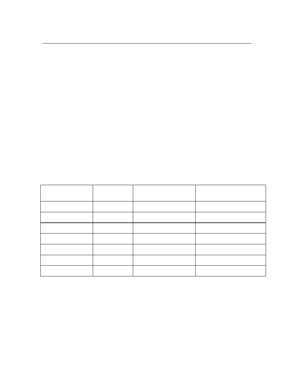
Resistance/Conductance Verification
Resistance Input
@ Cell Connector
3200 Range
Displayed Resistance
Displayed Conductance
1.000
Ω ± 0.5%
3.00 S *
1.000 ± .025
Ω
1.00 ± .04 S
10.00
Ω ± 0.2%
999.9 mS *
10.00 ± .119
Ω
100.0 ± 3.2 mS
100.00
Ω ± 0.1%
99.99 mS
100.0 ± 1.09
Ω
10.00 ± .11 mS
1000.0
Ω ± 0.1%
9999
µS
1.000 ± .011 K
Ω
1000 ± 11
µS
10.0 K
Ω ± 0.1%
999.9
µS
10.00 ± .11 K
Ω
100.0 1.1
µS
100.0 K
Ω ± 0.1%
99.99
µS
100.0 ± 2.1 K
Ω
10.00 ± .11
µS
1.000 M
Ω ± 0.1%
9.999
µS
1.00 ± .05 M
Ω
1.000 ± .021
µS
* No manual range change required. Instrument will display in correct range based on resistance
input
value.
YSI Incorporated
Model 3200
60