Bell & Gossett HT 50B SM B&G Series U Heat Exchangers Removable Bundle Design User Manual
Page 5
5
WARNING: It is extremely important to follow a
proper tightening sequence. If it is not followed, the
flanges can become cocked and a leak will result. When
tightening flanges with spiral wound gaskets, if cocking
occurs, the result can be deformation and non-repairable
damage to the gaskets in addition to a resultant leak.
Any gasket leak can result in potential injury to adjacent
personnel.
TIGHTENING TORQUES
Tightening tip: It is essential that the installer follows the
gasket manufacturer’s installation guidelines when
installing gaskets. Metallic gaskets, such as the spiral
wound gaskets, usually have special installation instruc-
tions. One of these instructions includes a special proce-
dure for tightening bolts/studs when installing new gas-
kets. The procedure recommends that the bolts/studs be
torqued in four stages.
a. Following the staggered tightening pattern, the bolts/
studs should be torqued to
1
/
3
of the recommended
tightening torque.
b. Same as a, the bolts/studs should be torqued to
2
/
3
of
the recommended tightening torque.
c. Same as a, the bolts/studs should be torqued to the
recommmended torque valve shown in the above chart.
d. Following the staggered tightening pattern the bolts/
studs torques should be checked for equilibrium since
the tightening of one bolt/stud can relieve the stress on
adjacent bolts/studs.
If after following the gasket manufacturer’s recommended
tightening procedure a leak still occurs, the bolts/studs
should be tightened in the torque increments shown until
the leak stops. The staggered tightening pattern is still
followed.
NOTE: When using spiral wound gaskets, both the head
and the shell/tank gaskets must be spiral wound. You can-
not mix one spiral wound and one compressed fiber gas-
ket on a heat exchanger.
13. Refer to “OPERATION” steps 5 and 6 regarding bolt re-
tightening after start-up.
14. Where frequent disassembly of the heat exchanger is
encountered, the use of new bolting in conformance with
dimension and ASTM specifications of the original design
is recommended.
1
9. Before reinserting the tube bundle into the shell or collar
of a tank, place the ring/tank gasket over the end of the
tube bundle and bring forward to the backside of the
tubesheet.
10. The tube bundle can be replaced using the tools and
reverse procedure given for bundle removal.
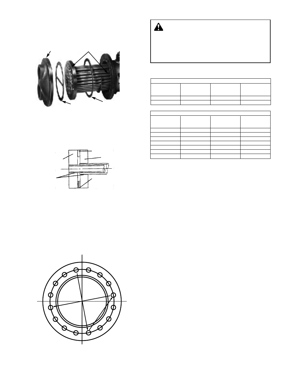
11. When installing a Diamondback™ double-wall tube bun-
dle, make sure the leak path drain hole in the spacer ring
between the two tubesheets is in the lowest position of
the tubesheet circle.
12. When replacing the heads, use a torque wrench to tighten
the bolts/studs and nuts. Use the following chart as
a guide. All torque values apply to well lubricated nut
bearing surfaces.
All bolted joints should be tightened uniformally and in a
diametrically staggered pattern as illustrated below:
1
2
3
4
6
9
14
7
15
12
5
10
13
8
11
16
START
TUBESIDE
TUBESHEET
SPACER RING
SHELLSIDE
TUBESHEET
CL TUBE
LEAK PATH
MECHANICALLY
ROLLED
TUBE
JOINT
DOUBLE-WALL TUBE JOINT
COMPRESSED FIBER GASKETS
Recommended
Bolt
Torque
Torque
Max.
Dia.
ft-lbs
Increment
Torque
1
/
2
"
40
5
60
5
/
8
"
80
5
120
SPIRAL WOUND GASKETS
Recommended
Bolt/Stud
Torque
Torque
Max.
Dia.
ft-lbs
Increment
Torque
1
/
2
"
1
40
1
5
11
60
5
/
8
"
1
80
1
5
1
120
3
/
4
"
120
1
5
1
200
7
/
8
"
200
10
1
320
1"
300
10
1
490
1
1
/
8
"
450
10
1
710
1
1
/
4
"
600
10
1000
HEAD GASKET
TANK GASKET
FRONT
HEAD
TUBE BUNDLE
(PARTIALLY REMOVED)