Temperature and spring pilot combination – Bell & Gossett HS 601G Pilot Operated Pressure and/or Temperature Steam Regulators Series 2000 User Manual
Page 8
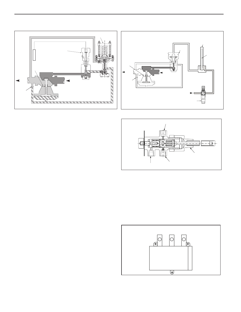
Temperature and Spring Pilot Combination
1. Install the temperature pilot next to the main valve.
2. Install a 1/4" NPT nipple between the outlet tapping
port of the temperature pilot and the inlet port of the
spring pilot.
3. The 1/4" feedback tapping port of the spring pilot
must be connected to the downstream piping:
• Use 1/4 black steel pipe for the feedback line.
• Install a 1/4 NPT shut off valve and union in the
feedback line to allow service of the pilot while
operating the system on the by-pass line.
• The feedback line must pitch away from the pilot to
avoid erratic operation and excessive fouling and to
eliminate water pockets.
4. When the regulator is used with a heat exchanger,
connect the feedback line (B) (see illustration on
page 6 to the heat exchanger shell. A tee fitting can
be installed in the heat exchanger for a vacuum
breaker connection.
5. Insert the sensing bulb of the temperature pilot so the
full length of the bulb is exposed to the fluid whose
temperature is being controlled.
a) Use a 1/2 NPT compression fitting to install the
bulb at the outlet of instantaneous heaters and in
the middle of storage tanks.
b) The preferred bulb mounting when installed in the
system piping is illustrated on page 7.
c) Optional dry well (separable socket) allows the
sensing bulb to be removed from the tank or piping
without draining the system.
• When using a dry well, coat the bulb with high
temperature grease or heat transfer compound,
to aid heat transfer.
• Make sure that bulb and dry well are fully inserted
into the fluid being controlled.
Spring Pilot
Outlet
Balance Tube
Self-Contained
Temperature
Pilot
Bleed
Orifice
Main Valve
Inlet
Pilot Inlet
Pneumatic Temperature and Air Pilot
Combination
Series 315 PNT Pilot
Series 240 PNT Pilot
1. Connect a regulated air supply to the "Reverse
Acting" inlet port of the 315 PNT pneumatic
temperature pilot.
2. Do not plug the "Direct Acting" inlet port of the
pneumatic temperature pilot. This port serves as
an air bleed.
3. Connect the output "Signal" port of the pneumatic
temperature pilot to the top of the AP-1A or AP-4A
pneumatic air pilot.
1. Connect a regulated air supply to the "Supply Air"
port of the 240 PNT pneumatic temperature pilot.
2. Connect the output "Branch Air" port of the pneumatic
temperature pilot to the top of the AP-1A or AP-4A
pneumatic air pilot.
Air Supply
Feedback Line
Balance
Tube
Outlet
Bleed
Orifice
Main Valve
Inlet
Pilot Inlet
Signal
AP Air
Pilot
Temperature
Sensor
315 PNT
Temperature
Pilot
Air PRV
Regulator
High Pressure
Supply Air
Main
Branch
Supply
Air Port
Branch
Air Port
y
y
y
y
y
y
y
y
y
y
y
y
y
y
y
y
yy
yy
y
y
y
y
y
y
y
y
y
y
y
y
y
y
y
y
yyy
yyy
yy
yy
yy
yyy
yyy
yy
yy
y
y
y
yy
y
yy
yy
y
y
y
y
y
yy
yy
yy
y
y
y
y
y
y
y
y
y
y
y
Signal Port
Reverse Acting
Signal Port
1/2" NPT
Direct Acting
Signal Port
8