Installation complete – Bell & Gossett HS 619B Series 754 Self-Contained Pressure Reducing Regulator User Manual
Page 3
Steam
Supply
B
J
F
H
E
D
Steam
Supply
K
L
Steam
Supply
J
C
M
N
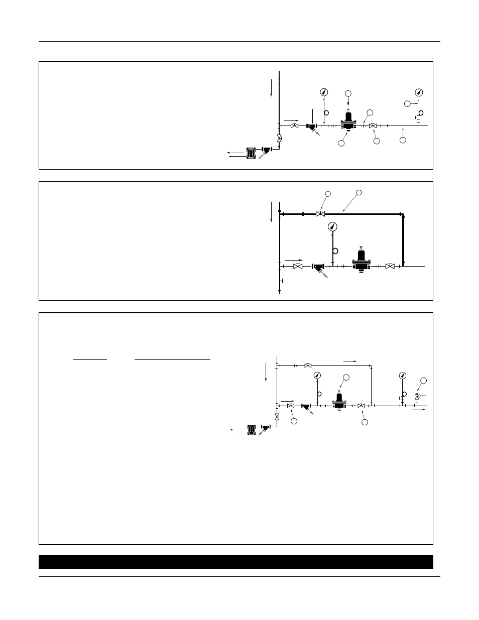
5. Optional
Install bypass line (K) with a globe valve (L), for
manual regulation during servicing.
6. Install a steam pressure relief valve (M).
Check to make sure that the set point
is correct:
Systems
Relief Valve Setting
Up to 35 psig
At least 5 psi (.35 bar)
(2.4 bar)
higher than outlet
pressure.
Over 35 psig
At least 10 psi higher
(2.4 bar)
than higher than outlet
pressure.
7. Check to make sure that the adjusting screw
(N) is backed out counterclockwise to relieve
spring tension. Slowly open gate valve (C)
and observe for leaks.
8. Slowly open the outlet gate valve (J). Turn
the adjusting screw (N) clockwise to increase
pressure to the set point. Allow the system to
stabilize. When set, tighten the regulating
screw locknut.
4 a. Position and install the Series 754 Regulator
(B) with the adjusting screw (H) on top.
b. Install a union (E), a gate valve (J), and a
pressure gauge (D) in the outlet piping (F).
INSTALLATION COMPLETE