Changing a thermostatic actuator on two-way valves, Caution – Bell & Gossett HS 504F Series 1141 Temperature Regulators User Manual
Page 6
6
CHANGING A THERMOSTATIC
ACTUATOR ON TWO-WAY VALVES
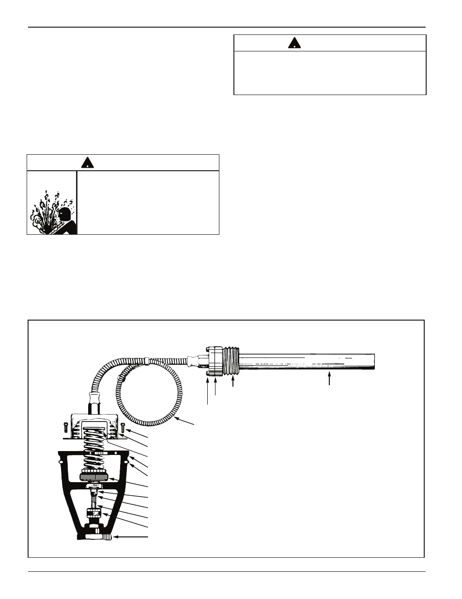
The Thermostatic Actuator used on the Series 1140 reg-
ulators is shown in Figure No. 11. All actuator parts
shown form one inseparable unit, except for the bulb
bushing with its gasket and fastening screws.
The Thermostatic Actuator will only control within the
temperature range stamped on the name plate, which is
fastened to the bellows housing.
If it is necessary to install a new actuator, to obtain a
higher or lower range, the following procedure should be
applied. Refer to Figure No. 11.
1. On units without a separable well, drain tank or pipe
line to a point below location of the thermostatic bulb.
2. Loosen the four (4) bulb bushing screws and slowly
break the bulb connection to make sure hot water
does not drain out, then remove four (4) screws and
take the bulb out of the bushing or well.
3. Turn temperature adjustment wheel to lowest position
(clockwise).
4. Cool bulb and bellows at least 20˚F (-6˚C) below low-
est temperature of range indicated on name plate.
5. Remove the bellows housing nuts and screws and lift
unit off bracket (keep bulb cool). Push down by hand
on upper valve stem plate until valve is shut. With a
pencil make a reference mark on the lower valve
stem, where stem enters stuffing box nut. This will
assist in checking total valve movement on opening
and also the thrust of the new thermostatic actuator.
6. Cool the new thermostatic actuator bulb which is to be
installed, at least 20°F (-6˚C) lower than the lowest
temperature marked on the name plate.
Actuators for valves in sizes 2-1/2" to 4" and with
ranges lower than 120° to 160°F (49 to 71°C) are
shipped with a clip, so that the bellows cannot expand
beyond limits in transit. Before removing this clip,
make sure you can compress bellows by hand. Only
then remove clip and attach housing to bracket, by
fastening the six (6) bellows housing screws. This
must be done quickly.
7. Recheck valve stem travel as outlined in paragraph
“Checking Valve Stem Travel” on page 5.
REGULATOR BODY
STUFFING BOX NUT
LOWER VALVE STEM
UPPER VALVE STEM
TEMPERATURE ADJUSTMENT WHEEL
BELLOWS HOUSING NUT
BRACKET
UPPER VALVE STEM PLATE
BELLOWS HOUSING
BELLOWS HOUSING SCREW
ARMORED CAPILLARY TUBING
BULB BUSHING SCREWS
GASKET
BULB BUSHING
THERMOSTATIC BULB
STEM ADJUSTMENT LOCK NUT
Figure No. 11
CAUTION
ALL SUPPLY VALVES MUST BE
TURNED OFF, SYSTEM PRESSURE
MUST BE REDUCED TO 0 psi (0 bar),
AND SYSTEM TEMPERATURE MUST BE
REDUCED BELOW 100˚F (38˚C) BEFORE
REMOVING THE BULB. FAILURE TO
FOLLOW THIS CAUTION MAY RESULT
IN SERIOUS BURNS.
!
CAUTION
REGULATORS OPERATING LOWER THAN 120˚ - 160˚
(49˚ - 71˚C) OR IN ROOMS ABOVE 100˚F (38˚C), THE
BELLOWS MUST BE COOLED UNTIL IT CAN BE
COMPRESSED BY HAND. FAILURE TO FOLLOW
THIS CAUTION COULD DESTROY THE ACTUATOR.
!