Bell & Gossett DN0162F HS Vented Boiler Feed Units Series HBF and VBF User Manual
Page 6
6
These close coupled vertical centrifugal pumps are equipped
with mechanical seals. If system has not been properly
cleaned prior to installation of pump, foreign matter such as
dirt, pipe scale, core sand, etc. may clog the impeller and
damage the seal. A strainer is recommended in return line to
pump. Pump must not be operated dry. Seals may be dam-
aged if operated without water present.
1. Close inlet line gate valve and operate pump momentarily
to remove as much liquid as possible from pump. Close
discharge line gate valve.
2. Shut-off and lock-out power.
3. Disconnect wiring to motor.
4. Make sure unit is cool enough that pump can be handled
safely. Open receiver drain to remove remaining liquid.
5. Loosen the four capscrews (4) holding pump case to
motor. Assure that pressure is relieved per caution note.
6. Remove four capscrews (4) holding pump case to motor
and lift motor and impeller out of pump case.
7. Remove pump/motor assembly and place on work bench.
8. Prevent the motor shaft from turning by inserting a large
screwdriver into the screwdriver slot located under the
plug on the rear motor endbell. Back the impeller off
(counter clockwise) using a rectangular bar or other flat
tool inserted between the impeller vanes.
9. Remove the rotating part of the mechanical seal from the
end of the shaft.
10. Remove seal holder (13) with stationary ceramic part of
mechanical seal and cup rubber from the end of the shaft.
11. Remove stationary ceramic part of mechanical seal and
cup rubber from recess in seal holder.
12. To install new seal, proceed as follows: Clean recess in
seal holder thoroughly. Insert new ceramic seat (grooved
face first) into the rubber seat cup. Lubricate the outside of
the cup and seal holder recess with soapy water. Install
the ceramic/cup assembly into the seal holder, making
sure the assembly bottoms evenly. When repairing "B"
style pumps manufactured between 1983 through 2001,
orient wire spacer eye to the left midway between motor
lugs. Replace seal holder over wire spacer on the face of
the motor, maintaining concentricity with motor face.
Pumps manufactured in 2002 or later, are manufactured
with DP1966 seal holder and do not require the wire
spacer. Pumps using DP1966 should orient the seal holder
tab to the left, midway between motor lugs. Using a clean,
lint-free cloth, wipe the mating surfaces of the seal clean
of any foreign matter. Moisten the carbon section of the
rotating part of the seal and lubricate the I.D. with soapy
water. Place onto shaft to seat against the ceramic.
13. Hold motor shaft as described in #8 and replace the im-
peller on the shaft (clockwise rotation) making sure it is tight.
14. Orient motor for pump reassembly with conduit opening to
the left. When mounting the pump case, discharge should
be 90˚ to the right of the wire spacer eye or (90˚ to the tabs
on DP1966) and conduit opening on motor. Use care to
insure tight gasket fit to prevent water leakage. When
replacing pump case, the wire spacer eye or the tabs on
DP1966 should seat in pump case notch. If this does not
occur inspect for proper alignment and reassemble.
15. Replace four capscrews (4). Tighten down capscrews
evenly to avoid damage.
16. Reconnect pump bleed line (where applicable) and motor
wiring.
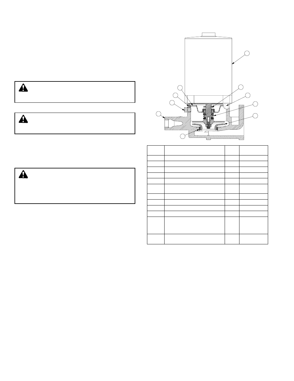
PUMP SERVICE INSTRUCTIONS FOR WATCHMAN CENTRIFUGAL PUMPS
WARNING / HIGH VOLTAGE: Disconnect and lock
out power before connecting or servicing unit.
Failure to follow these instructions could result in serious
injury or death.
CAUTION / HOT SURFACES: Surfaces are hot
when system is in operation. Do not touch hot re-
ceiver, let unit cool before servicing. Failure to follow
these instructions could result in injury or property damage.
CAUTION / PRESSURIZED SYSTEM: Operating
system may contain very hot water under pressure.
Close inlet and open drains before servicing. When ser-
vicing, loosen screws and move components to assure
pressure is relieved before removing screws. Keep drains
open during servicing. Failure to follow these instructions
could result in injury or property damage.
1
10
7
3
4
8
6
9
5
2
Item
No.
Part
Number
Description
Req'd.
No.
1
Motor
1
/
3
hp, 1 ph. 3500 rpm
1
180096
2
Seal Holder
1
DP1966
3
Seal*
1
—
4
Impeller
1
DP0321
5
Head Gasket*
1
DG0092
6
Pump Case with
wearing ring
1
DP1665
7
Capscrew
1
DJ0083
8
Wear Ring
1
DP0482
9
Pipe Plug
1
/
4
" (6 mm)
1
P39040
10
Water Slinger
1
DP0848
Seal kit including
mechanical seal, head
*
gasket, & case to
receiver gasket
1
180013
Complete pump and
motor assembly
1
180001
Order Replacement Parts by Description and Part No.
Specify Serial No. shown on nameplate.