Description – Bell & Gossett DN0162F HS Vented Boiler Feed Units Series HBF and VBF User Manual
Page 2
DESCRIPTION
Boiler feed units are designed to pump water into an operating
boiler. The pumps are controlled by level controls on the boiler.
Boiler feed units are normally sized to accommodate system
surges and also to provide for the addition of fresh water as
required.
Series VBF and HBF units are standardized feed units intended
for application to low pressure boilers. Pump discharge pres-
sures are 20 psi (1.4 bar), 25 psi (1.7 bar) and 30 psi (2 bar) de-
pending upon model specified. Receivers are heavy gauge, non-
code steel. HBF receivers are provided with the Hoffguard™
corrosion resistant coating for longer life.
Receivers are non-code steel.
PRELIMINARY INSPECTION
Assure that there is no shipping damage.
Assure that nameplate ratings agree with job specifications
and actual conditions.
Remove all plastic shipping plugs from receiver and pumps.
HANDLING
Use care in installing unit.
LOCATION
Place unit for easy access to all parts. Allow adequate space
for servicing. Check ambient conditions.
NOTICE / TEMPERATURE LIMITS
Motors are designed to operate in 104˚F (40˚C) max. ambient.
Insulate or ventilate as required.
PIPING (General)
Pipe the unit per the above Piping Diagram. Locate and sup-
port piping so as to not load the pump discharge.
PIPING (Returns)
Gravity return lines from system must be properly pitched
down to unit inlet. Returns must also be trapped to pre-
vent steam entry into the unit. An inlet basket strainer is
recommended.
PIPING (Vent)
Install a vent pipe to atmosphere. Pipe to be size of vent port
on unit. Do not restrict or reduce vent opening or exceed 20
feet vertical height unless an overflow connection is provided.
PIPING (Overflow)
Pipe overflow connection to drain. When condensate temper-
ature exceeds 200˚F (93˚C) an overflow loop must be used.
PIPING (PUMP DISCHARGE)
Connect the pump discharge(s) to the boiler in accordance
with the above diagram. This piping must be coordinated with
electrical controls in the case of multiple pumps and multiple
boilers.
Boiler feed systems are supplied to meet a wide variety of sys-
tem specifications. The electrical controls and piping systems
must be coordinated.
WATER MAKE-UP
A mechanical valve is furnished for water make-up. A “Y”
strainer is recommended ahead of this valve. See page 5 for
detailed information. The inlet water pressure must not exceed
30 psi (2.0 bar).
ELECTRICAL WIRING & CONTROLS
Connect power wiring per National Electrical Code. Recheck
nameplate vs. specifications and conditions. All single phase
motors have internal thermal protection.
All series VBF units are furnished with 115/230V 1 Phase,
60Hz motors. Factory motor wiring is for 115V. To convert
motor to 230 volt, follow motor manufacturers instructions.
CAUTION / NOT A CHEMICAL PUMP: Inject boiler
feed compounds from chemical feed tank into boiler
feed piping — never into boiler feed tank. Failure to fol-
low these instructions could result in injury or property
damage.
WARNING / HIGH VOLTAGE ELECTRICITY: Dis-
connect and lock out power before connecting or
servicing unit. Failure to follow these instructions could
result in serious injury or death.
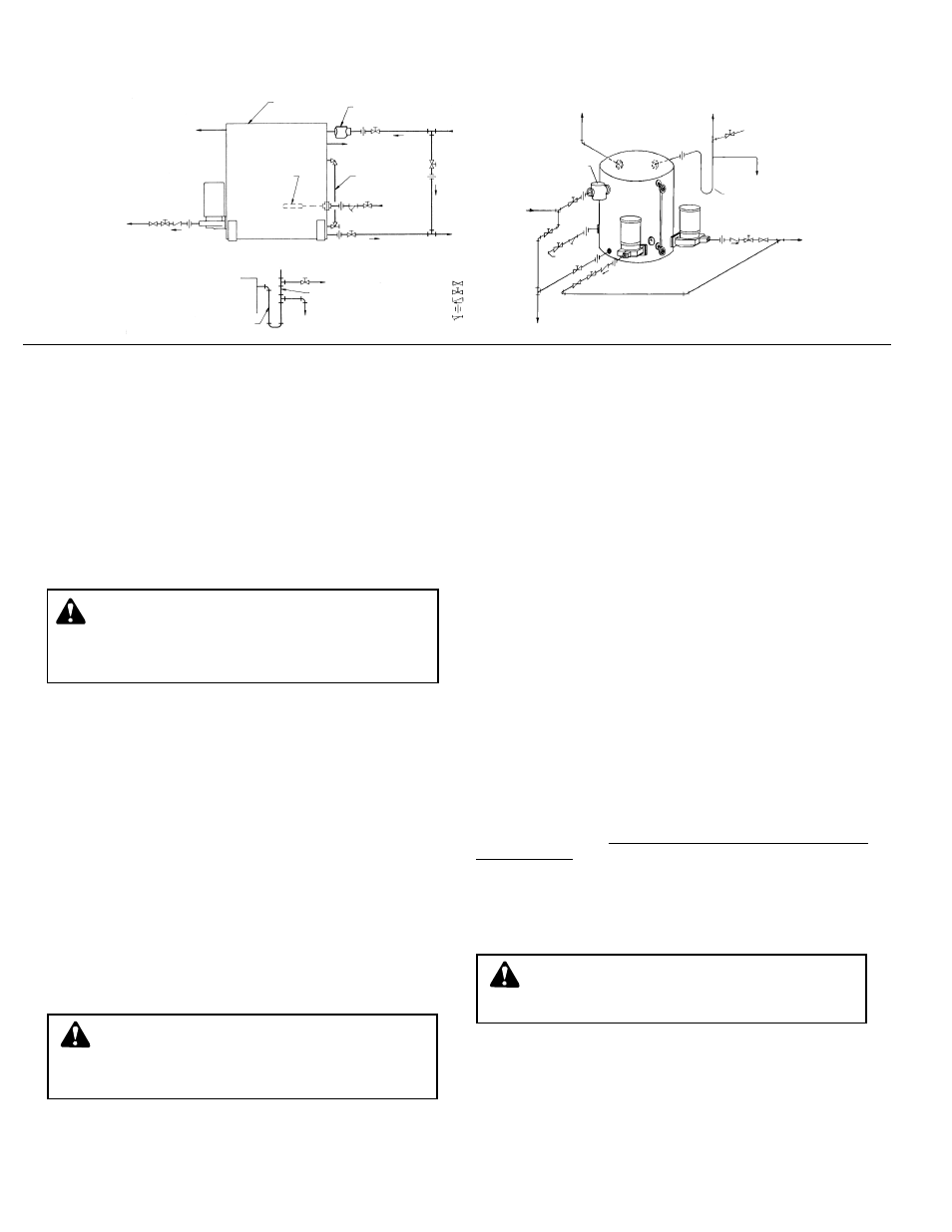
INSTALLATION AND DESCRIPTION (TYPICAL PIPING DIAGRAM)
WARNING: EXPLOSIBLE
Do not pressurize receiver. Isolate receiver during
leak test. Do not plug overflow. Do not restrict vent opening
to atmosphere. Open valves slowly. Failure to follow these
instructions could result in serious injury or death.
2
Pump
Discharge
SERIES VBF
SERIES HBF
Full Size Air Vent
To Atmosphere
Boiler Feed
Receiver
Basket Strainer
Overflow
(See Detail)
Condensate Return
From System
Gauge
Glass
Make-Up
Water
Supply
(See Note 1)
NOTE:
1. Inlet water pressure
should not exceed 30
psi (2.0 bar). For water
systems in excess of 30
psi (2.0 bar), use a Bell
& Gossett #6 Pressure
Reducing Valve, set at
30 psi (2.0 bar).
Boiler
Feed Pump
Receiver
Overflow Loop
To Drain
Vent
OVERFLOW LOOP DETAIL
Loop Fill
Syphon Breaker
Vent To Atmosphere
Vent
Loop Fill
To Drain
Overflow Loop
To Drain
Water
Make-Up
Inlet Strainer
Plug Cock
Gate Valve
Check Valve
Union
Y-Strainer
Return From
System
Mechanical
Make-Up Valve
To
Drain