Dsk-978, Make-up water valve instructions, Make-up water valve – Bell & Gossett DN0162F HS Vented Boiler Feed Units Series HBF and VBF User Manual
Page 5
5
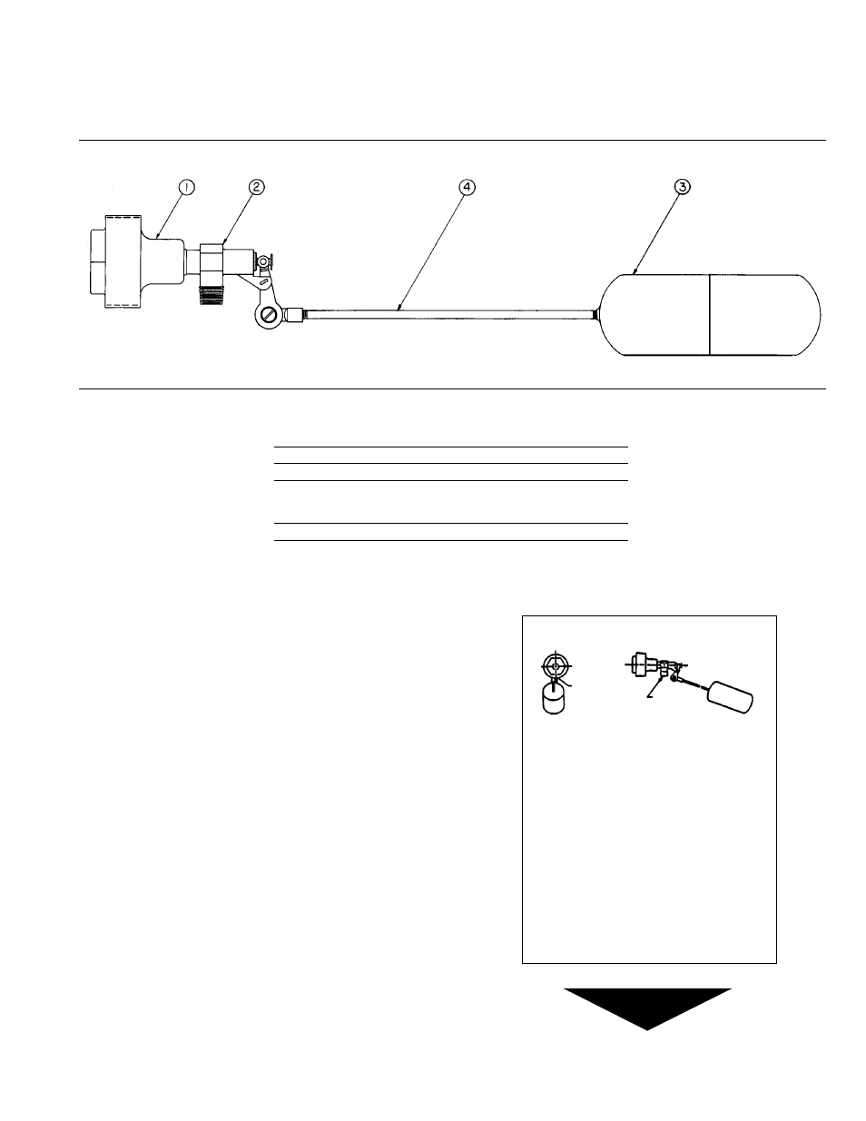
MAKE-UP WATER VALVE
INSTRUCTIONS
Item
No.
Part
Number
Description
Req’d.
No.
1, 2, 3 & 4
Float Valve Assembly
1
DL1634
3
Float
1
DA0164
2 & 4
Float Valve Only
1
DV1024
(Less float and
adapter)
1
Adapter
1
DL1750
Adjustment — The make-up water valve is factory set to main-
tain receiver water level at approximately
1
/
2
full. When systems
require a large percentage of make up water, the float setting
should be raised to utilize full receiver capacity. When large per-
centages of returns from the system are available the float setting
may be lowered to not less than 4" (101 mm) above the top of the
pump suction opening.
A float arm pivot allows the float setting to be raised or lowered.
The valve must be removed to change float setting. This adjust-
ment can be accomplished by loosening the screw on the float
arm pivot and setting the arm position to the level desired. When
the desired setting is attained interlock the toothed pivot and
tighten the screw to secure the setting. Reinstall valve in the
receiver.
Maintenance — The “Y” strainer should be cleaned periodically.
During the first few weeks of operation the strainer screen should
be checked and cleaned every week. The screen can be removed
for cleaning through the strainer’s branch connection. The valve
should be observed for tight closing and proper level on a period-
ical basis.
Pressure Limitation — Inlet water pressure to the make up valve
should not exceed 30 psi (2.0 bar). For water systems in excess
of 30 psi (2.0 bar), installation of a Bell & Gossett #6 pressure
reducing valve to reduce make up water pressure below 30 psi
(2.0 bar) is recommended.
Mounting — The valve is mounted on a 2
1
/
2
" (64 mm) NPT pipe
plug located on the side of the receiver. The entire assembly may
be removed through the tapped opening. The “B” stamped on
the valve mounting bushing should always be at the bottom of
the installed plug to assure proper alignment.
Make-up Water Valve
This unit is equipped with an internal water make-up
valve pre-set at the factory.
The valve may be readjusted to add make-up water at
other water levels. Remove assembly to readjust level.
NOTICE: PRESSURE LIMITATION.
Inlet water pressure should not exceed 30 psi. For water
systems in excess of 30 psi use a Bell & Gossett #6
Pressure Reducing Valve adjusted to 30 psi.
NOTICE: ALIGNMENT REQUIRED.
The “B” stamped on the valve mounting bushing should
always be at the bottom of the installed valve.
MAKE-UP WATER CONNECTION
NOTE:
INSTALL “B” (BOTTOM)
IN LINE WITH
WATER DISCHARGE
IDL001
DN0122
DSK-978
Fig. 2
STAMP “B”
WATER
DISCHARGE