Opera tion and maintenance – Bell & Gossett DN0137D Domestic Pump Vacuum & Boiler Feed Unit Series VCMD User Manual
Page 5
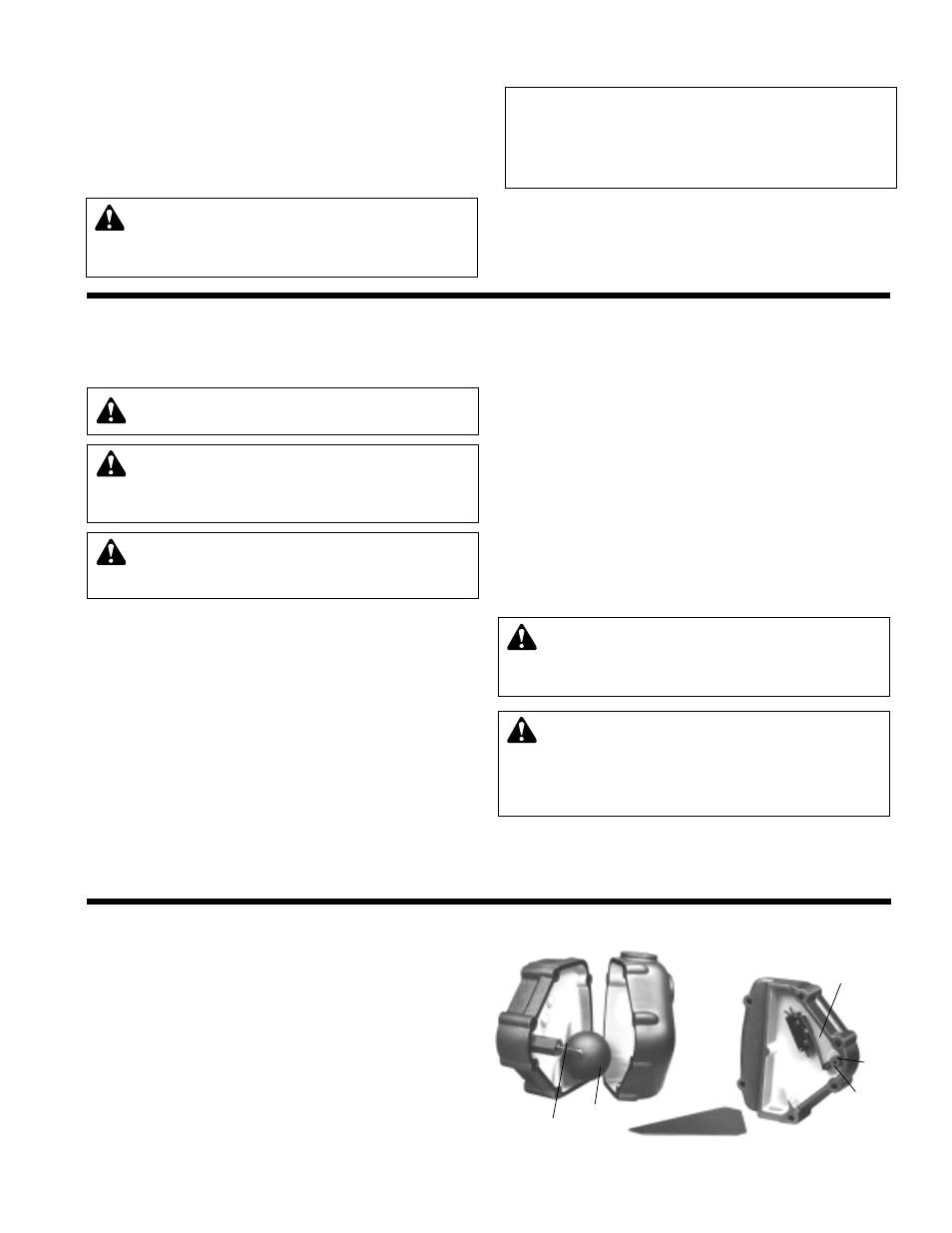
HURLING CHAMBER FLOA
T SWITCH ADJUSTMENT
The switch which contr
ols the hurling water makeup valve is located
inside the float housing near the vacuum unit overflow.
The switch is under a triangular cover plate which is retained by one #6
screw (loosen bolts retaining the cover edges only if necessary). The
actuating cam can be rotated for testing by using a screwdriver in the
slot provided.
Adjusting the switch location so that the switch snaps at approxi-
mately mid-range of the cam travel. The #6 screw near the cam goes
thru a slot in the switch mounting plate. Loosen this screw (and the
farthermost screw thru the switch) to permit adjustment of the switch-
ing position. Tighten screws and recheck operation after making any
adjustment.
The cam should be positioned on the shaft for maximum switch roller
movement in operation. The cam is retained by a socket set screw.
Replacement seal tube assemblies are available in case of leakage
around the float pivot shaft.
OPERA
TION AND MAINTENANCE
Operators must be familiar with all sections of this manual to under
-
stand the operation of the unit.
Hot water, steam and electricity can be hazardous.
LUBRICA
TION
The only pump bearing r
equiring lubrication is the ball bearing in the
motor support just below the flexible coupling. It has a reservoir, which
is filled with moisture resistant high temperature grease.
Remove pipe plug in motor support and add approximately 3 ounces
of Shell Alvania RL 2 grease (or equivalent) from once a year (normal)
to twice a year for extremely hot conditions. Do not use ordinary
grease.
NOTICE/AUTO REST
ART
Single phase motors will r
estart automatically after thermal overload
protector trips.
Overload thermal relays in starters must be reset manually.
GAGE GLASS MAINTENANCE
(Vented Systems)
Clean gage glass as r
equired using commercial glass cleaner. Dilute
muratic acid may be used if required (observe handling precautions).
Never clean gage glass with wire brushes, scrapers or harsh abrasives.
Do not reuse gage glass or packing or seals.
Immediately replace glass which is broken, cracked, chipped,
scratched or otherwise damaged. Inspect periodically with a bright
concentrated light. Anything which glistens and catches the fingernail
or any star-shaped or crescent-shaped mark which glistens is cause
for replacement. Any gage glass which appears cloudy or roughened
and will not respond to cleaning procedures should be replaced.
When replacing gage glass, use new packings specified for this use.
Install glass with sufficient end clearance for expansion (keep glass to
metal clearance at each end) and tighten nuts just enough to avoid
leakage (do not over tighten).
INSPECTIONS
A pr
operly installed unit should function unattended for long periods of
time. Periodic checks to assure proper operation are highly recom-
mended. Refer to trouble shooting section when necessary.
A variety of control options are available and are furnished in accor-
dance with user specifications. Refer to wiring diagrams (when fur-
nished) to determine control switch settings.
The inlet strainer (when furnished) is intended to protect the pump and
system. Periodic cleaning should be included in the maintenance
schedule. Check frequently in new systems.
W
ARNING: EXPLOSIBLE
The installer boiler feed unit becomes an integral part of the
boiler system. Boiler operation and maintenance requires specific
skills and training and may require licensing or certification. The
boiler feed unit must be operated and maintained so as not to jeop-
ardize the boiler operation. Failure to follow these instructions could
result in serious injury or death.
W
ARNING: EXPLOSIBLE
Do not pr
essurize receiver. Isolate receiver during leak test.
Do not plug overflow. Do not restrict vent opening to atmosphere.
Open valves slowly. Failure to follow these instructions could result
in serious injury or death.
5
12. Check that the pump discharge pressure exceeds the maximum
operating pressure of the boiler.
13. Manually move the make-up water float indicator and assure that
the make-up solenoid admits water.
14. Manually move the low water cut-off float switch indicator to check
for pump shut-off.
15. Make sure that the make-up valve on the vacuum producer has
operated and filled the hurling chamber to 2" to 6" below the over-
flow (recommended).
16. Remove start-up label (below) from panel (if applicable) after com-
plying with instructions.
17. If possible, observe operation thru several cycles.
CAUTION:
DO NOT RUN DRY.
SEAL DAMAGE MAY OCCUR
Inspect pump seal r
egularly for leaks. Replace as required. Failure
to follow these instructions could result in injury or property
damage.
ELECTRICIAN/INST
ALLER/OPERATOR
REMOVE AND DESTROY THIS T
AG AFTER —
1. ASSURING THAT ALL PUMPS ROTATE CLOCKWISE PER ARROWS CAST
ON VOLUTES. (JOG PUMP MOMENTARILY TO TEST – INTERCHANGE
ANY TWO MOTOR POWER WIRES TO REVERSE 3PH MOTORS.)
2. ASSURING THAT SHIPPING LOCKS HAVE BEEN REMOVED FROM ALL
FLOAT SWITCHES.
W
ARNING: HIGH VOLTAGE
Disconnect and lock out power befor
e connecting or servic-
ing unit. Failure to follow these instructions could result in serious
injury or death.
CAUTION: SUBSEQUENT DAMAGE
A unit showing symptoms of possible pr
oblems (overflow,
noise, leaks, vibrations, continual operation, etc.) must be corrected
immediately. Failure to follow these instructions may result in full lia-
bility for subsequent injury or property damage.
SAFETY INSTRUCTIONS
SEE COVER OF THIS MANUAL
FLOAT ROD
MICRO SWITCH
CAM
FLOAT BALL
CAM SET
SCREW