Description, Boiler feed system – Bell & Gossett DN0137D Domestic Pump Vacuum & Boiler Feed Unit Series VCMD User Manual
Page 3
DESCRIPTION
The Series VCMD family of units consists of various combinations of
boiler feed units combined with Domestic Series MJ vacuum pro-
ducers. The vacuum producer may be mounted directly on the boiler
feed unit (STyle A) or the units may be independently mounted with field
piping between the units (Style B). The boiler feed units can be con-
structed with cast iron or steel receivers in many of the standard con-
figurations offered as Domestic boiler feed units.
The vacuum producer acts in response to selector switch settings and
system vacuum also functions to remove excess water from the boiler
feed tank. Various controls are supplied in accordance with system
specifications and system requirements. Electrical panels are normally
supplied and specific wiring diagrams are supplied with each vacuum
producer electrical panel.
The boiler feed system functions like a standard vented boiler feed sys-
tem. Again, various control options are available to match system
specifications. Electrical panels and electrical diagrams are normally
furnished.
The boiler feed units are designed to pump water into an operating
boiler. The pumps are controlled by level controls on the boiler. Low
water cut-off switches and alarms are often supplied (optional).
Receivers are non-code cast iron or steel.
PRELIMINAR
Y INSPECTION
Assur
e that there is no shipping damage.
Assure that nameplate ratings agree with job specifications and actual
conditions.
HANDLING
Use caring in installing unit.
LOCA
TION
Place unit for easy access to all parts. Allow adequate space for
servicing. Check ambient conditions.
NOTICE/TEMPERA
TURE LIMITS
Motors ar
e designed to operate in 104°F max. ambient. Insulate or
ventilate as required.
BOILER FEED SYSTEM
PIPING (General)
Pipe the unit per the Piping Diagram. Locate and support piping so as
to not load the pump discharge.
PIPING (
Return)
Gravity r
eturn lines from the system must be properly pitched down to
unit inlet. Returns must also be trapped to prevent steam entry into the
unit. An inlet basket strainer is recommended.
FLOA
T SWITCHES
Floats ar
e locked in place to prevent damage during shipment. Remove
shipping locks. Check factory settings. Floats are adjustable for various
levels of operation. The water make-up float switch should “make” at a
higher level than low water cut-off switch “breaks”.
V
ACUUM SYSTEM
PIPING (General)
Pipe the unit per the Piping Diagram shipped with the unit or as shown
herein. Locate and support piping so as to not load the pump discharge.
PIPING (
Suction) (Style B)
Use a suction line at least as lar
ge as the unit inlet fitting. Vacuum
storage tanks will reduce system surges or short cycling and a vertical
tank can trap liquids and solids.
PIPING (V
ent)
Install a vent pipe to atmospher
e. Pipe to be size of vent port on unit.
Do not restrict or reduce vent opening or exceed 20 feet vertical height
unless an overflow connection is provided.
PIPING (O
verflow)
Pipe overflow port to drain.
V
ACUUM SWITCH ADJUSTMENTS
V
acuum switches, when furnished, are factory adjusted and tested for
the specified operating range. If settings must be readjusted, refer to
manufacturer’s instructions.
HURLING W
ATER MAKE-UP AND CONTROL
The hurling water level is automatically contr
olled by a solenoid valve
actuated by a float switch.
Connect the water make-up assemblies to city water. Use piping at
least as large as the valve piping provided. Install a manual fill valve if
not included on the unit. The vacuum producer and the boiler feed unit
have separate make-ups.
To operate at a high vacuum, the hurling water must be at a low tem-
perature resulting in a low vapor pressure. Cooling water can be auto-
matically admitted by using an optional temperature limit switch. This
switch actuates the solenoid valve if the temperature rises above a
preset point.
The optional condensate Temperature Limit Switch will stop normal
operation of the vacuum unit when condensate exceeds the set point
temperature (usually 160ºF). Vacuum is not normally required when the
system is up to temperature and operation of the vacuum pumps with
hot condensate results in condensate loss due to evaporation.
INTERCONNECTING PIPING
On style B units, the inter
connecting piping between the boiler feed
unit and the vacuum producer must be the size of the vacuum pro-
ducer inlet. The two vacuum inlets on duplex vacuum producers must
be connected to the boiler feed tank.
ELECTRICAL WIRING & CONTROLS
Connect power wiring per NEC. Recheck nameplate vs. Specifications
and conditions. All single phase motors have internal thermal
protection.
Three phase motors must be use starters with properly sized overload
relays. Overload relays furnished are designed for manual reset.
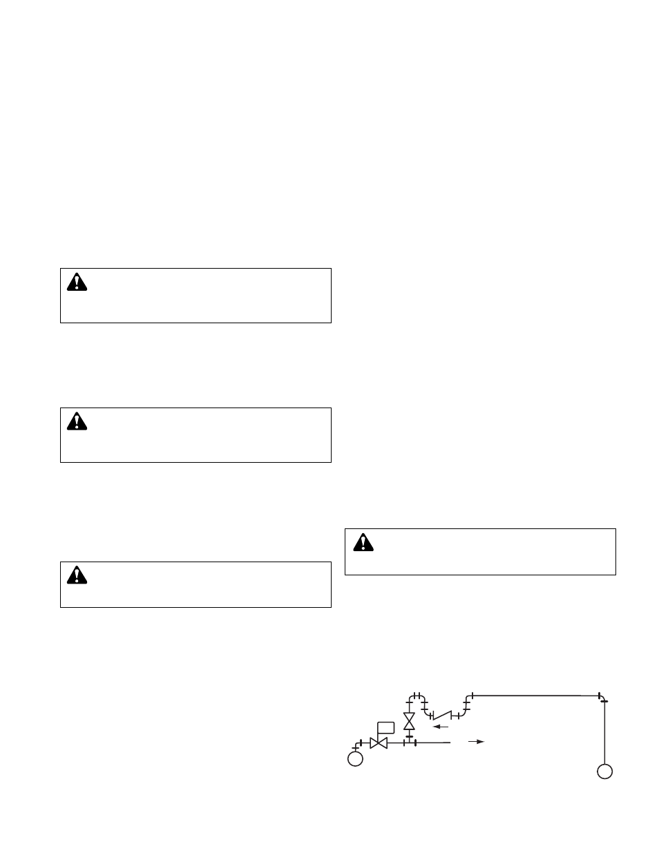
EQUALIZING LINE
A vacuum may be formed on radiation side of system when steam
stops flowing in mains. This vacuum may be higher than return line
vacuum, which would prevent condensate from flowing back to pump.
To correct this in an unzoned system, install equalizer line as shown in
Figures 1 thru 3. To correct this in a zoned system, also install equali-
zer line for each zoned section or install a vacuum breaker on supply
line on radiation side of each zone valve.
W
ARNING: EXPLOSIBLE
Do not pr
essurize receiver. Isolate receiver during leak test.
Do not plug overflow. Do not restrict vent opening to atmosphere.
Open valves slowly. Failure to follow these instructions could result
in serious injury or death.
3
CAUTION:
UNIT LIFTING EYE
Use unit lifting eyes only to lift unit as shipped fr
om factory.
Unit must be empty and disconnected from pipes, anchors and
other restraints. Use proper rigging procedures. Failure to follow
these instructions could result in injury or property damage.
CAUTION:
NOT A CHEMICAL PUMP
Inject boiler feed compounds fr
om chemical feed tank into
boiler feed piping – never into condensate tank. Failure to follow
these instructions could result in injury or property damage.
W
ARNING: HIGH VOLTAGE ELECTRICITY
Disconnect and lock out power befor
e connecting or servic-
ing unit. Failure to follow these instructions could result in injury or
property damage.
FIG. 4 EQUALIZING CONNECTIONS FOR ZONED SYSTEMS
ZONE CONTROL
VALVE
STEAM MAIN
M
TO ZONE
RETURN MAIN