Putting the unit into ser vice, Over view – Bell & Gossett DN0137D Domestic Pump Vacuum & Boiler Feed Unit Series VCMD User Manual
Page 4
PUTTING THE UNIT INTO SER
VICE
1.
Assure that the unit is piped in accordance with instructions.
2. Isolate tank before performing any system leak test. Do not pres-
surize the tank as part of the leak test. Failure to do this can result
in serious injury or death.
3. Check floats for free operation. Assure that shipping locks have
been removed.
4. Check power leads in accordance with wiring diagram enclosed in
control cabinet (when furnished).
5. Install drain plugs.
6. Fill receiver (upper compartment on Series VLR) half full of water to
prime pump(s) and prevent possible damage to pump seals. Avoid
freezing conditions after unit receiver has been filled.
7. Check for proper rotation of all three phase motors. Rotation must
be clockwise looking down on the motor as indicated by direc-
tional arrow on pump casting. If pump runs backwards, inter-
change two wires (3 phase only).
8. Throttle plug cock in discharge line until pressure at pump (while
pump is discharging) approaches pump rated pressure. Tighten
plug nut to secure adjustment.
9. Connect the water make-up assemblies to city water. Use piping at
least as large as the valve piping provided. Provide a manual fill
valve if not included on the unit. Vacuum producer and boiler feed
unit have separate make-ups.
10. Vacuum switches are factory set per job specifications and re-
adjustment should not be necessary. Refer to switch manufac-
turer’s literature for details of adjusting procedure. If resetting is
required, it is helpful to disconnect wiring and set one switch at a
time. The “lead” switch must make and break at a slightly deeper
vacuum than the “lag” switch.
Typical vacuum switch settings are as follows:
Switch
Make
Break
LEAD
3"
8"
LAG
2
1
/
2
"
8"
11. Assure that the controls on and related to the boiler match the con-
trol systems provided on the unit (see the wiring diagram furnished)
(applicable when electrical control panel is furnished).
W
ARNING: MAINTAIN BOILER SAFETY FEATURES
When connecting the boiler feed unit to the boiler
, assure
that all boiler safety controls (burner cutoff, etc.) are and remain
operational. With certain control arrangements, dedicated boiler
controllers are required for the boiler feed pumps. Failure to follow
these instructions could result in serious injury, death or extensive
property damage.
W
ARNING: EXPLOSIBLE
Do not pr
essurize receiver. Isolate receiver during leak test.
Do not plug overflow. Do not restrict vent opening to atmosphere.
Open valves slowly. Failure to follow these instructions could result
in serious injury or death.
4
W
ARNING: HIGH VOLTAGE
Disconnect and lock out power befor
e connecting or servic-
ing unit. Failure to follow these instructions could result in serious
injury or death.
CAUTION:
DO NOT REVERSE
Reverse operation can cause extensive damage to pumps.
Jog the motor to test for direction of rotation. Failure to follow these
instructions could result in injury or property damage.
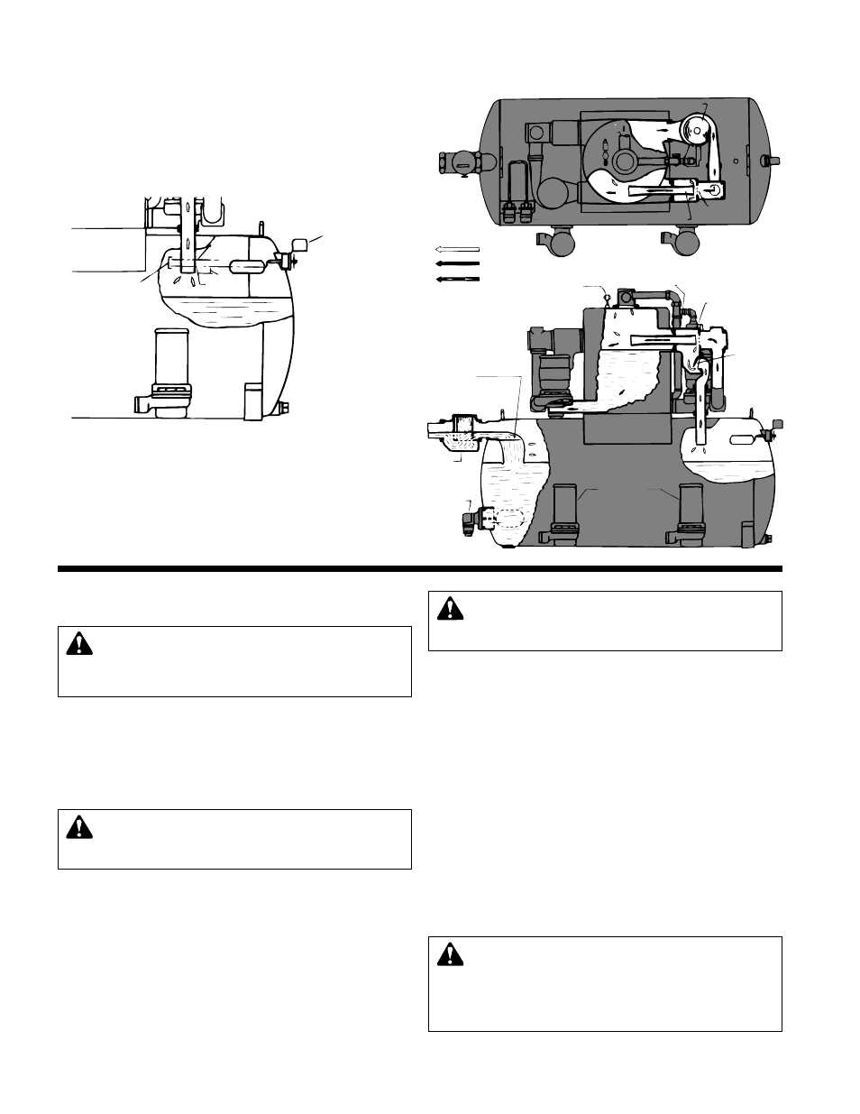
OVER
VIEW
SIMPLE AUTOMATIC OVERFLOW CONTROL
If excess condensate enters the boiler feed r
eceiver, the water level will
rise above a preselected height, and float switch will actuate the air
pump. The resulting vacuum draws excess water through the air suc-
tion line into the separation chamber of the air pump from where it sim-
ply overflows to a drain. An overflow pump is not necessary or recom-
mended unless the drain is located above the overflow of the air pump.
If such a drain exists, an overflow pump can be furnished. The float
switch will then start the overflow pump instead of the air pump.
FIG. 5 ADJUSTMENT OF OVERFLOW CONTROL FLOA
T SWITCH
1.
Close inlet valve. Set all selector switches to “Off”.
2. Add water to condensate receiver until it is flooded.
3. Operate air pump to bring water level to bottom of air suction (lift)
pipe; turn selector switch(es) to “Off”.
4. Adjust float switch to open about
1
/
2
" above this level.
5. Set the other quadrant as close as possible for minimum differential.
OVERFLOW
SWITCH
CONTACTS
CLOSE
1/2"
CONTACTS
OPEN
ADJUST SWITCH
FOR MINIMUM
DIFFERENTIAL
AIR
VENT
VACUUM PUMP IMPELLER
MULTI-JET
NOZZLE
VENTURI
VACUUM SWITCHES
AIR
WATER
AIR & WATER
VACUUM PUMP
SOLENOID VALVE FOR
HURLING WATER
CONTROL
OVERFLOW (GRAVITY)
FLOAT SWITCH FOR
HURLING WATER
CONTROL
AIR SUCTION
CHECK VALVE
DEAERATING CASCADE
BAFFLE
HURLING
WATER
AIR
SUCTION
AND OVERFLOW
CONDENSATE
BOILDER FEED RECEIVER
BOILER FEED
PUMPS
INLET
STRAINER
(OPTIONAL)
MECHANICAL
WATER MAKE
UP VALVE