Pam8407 new product, Application information – Diodes PAM8407 User Manual
Page 7
PAM8407
Document number: DS36815 Rev. 1 - 2
7 of 12
www.diodes.com
January 2014
© Diodes Incorporated
PAM8407
New Product
A PRODUCT LINE OF
DIODES INCORPORATED
2x3W Stereo Differential Input Class D Audio Amplifier
with Up/Down Volume Control
Application Information
Maximum Gain
As shown in block diagram, the PAM8407 has two internal amplifiers stage. The first stage's gain is externally con-figurable, while the second
stage's is internally fixed in a fixed-gain, inverting configuration. The closed-loop gain of the first stage is set by selecting the ratio of Rf to Ri while
the second stage's gain is fixed at 2x. Consequently, the differential gain for the IC is
A
VD
= 20*log [2*(Rf/Ri)]
The PAM8407 sets maximum Rf=218kΩ and minimum Ri=27kΩ, thus the maximum closed-gain is 24dB.
UP/DOWN Volume Control (DVC)
The PAM8407 features a UP/DOWN volume control which consists of the UP and DOWN pins. An internal clock is used where the clock
frequency value is determined from the following formula:
f
CLK
= f
OSC
/ 2
13
The oscillator frequency f
OSC
value is 250kHz typical,with ±20% tolerance. The DVC’s clock frequency is 30Hz (cycle time 33ms) typical.
Volume changes are then effected by toggling either the UP or DOWN pins with a logic low. After a period of 1 cycle pulses with either the UP or
DOWN pins held low, the volume will change to the next specified step, either UP or DOWN, and followed by a short delay. This delay decreases
the longer the line is held low, eventually reaching a delay of zero. The delay allows the user to pull the UP or DOWN terminal low once for one
volume change, or hold down to ramp several volume changes. The delay is optimally configured for push button volume control.
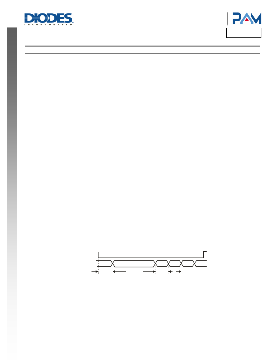
If either the UP or DOWN pin remains low after the first volume transition the volume will change again, but this time after 10 cycles. The followed
transition occurs at 4 cycles for each volume transition. This is intended to provide the user with a volume control that pauses briefly after initial
application, and then slowly increases the rate of volume change as it is continuously applied. This cycle is shown in the timing diagram shown in
figure 1.
There are 32 discrete gain settings ranging from +24dB maximum to -80dB minimum. Upon device power on or applied a logic low to the SD pin,
the amplifier's gain is set to a default value of 12dB. Volume levels for each step vary and are specified in Gain Setting table on page 7.
If both the UP and DOWN pins are held high, no volume change will occur. Trigger points for the UP and DOWN pins are at 70% of VDD minimum
for a logic high, and 20% of VDD maximum for a logic low. It is recommended, however, to toggle UP and DOWN between VDD and GND for best
performance.
1 c y c le
1 0 c y c le s
4 c y c le s
UP/DN
VOLUME
LEVEL
4 c y c le s
Figure 1.Timming Diagram
Shutdown operation
In order to reduce power consumption while not in use, the PAM8407 contains shutdown circuitry that is used to turn off the amplifier's bias
circuitry. This shutdown feature turns the amplifier off when logic low is placed on the SD pin. By switching the SD pin connected to GND, the
PAM8407 supply current draw will be minimized in idle mode. The SD pin cannot be left floating due to the pull-down internal.