Pam8124 new prod uc t, Performance characteristics, Application information – Diodes PAM8124 User Manual
Page 7
PAM8124
Document number: DS36627 Rev. 1 - 2
7 of 15
October 2013
© Diodes Incorporated
PAM8124
NEW PROD
UC
T
A Product Line of
Diodes Incorporated
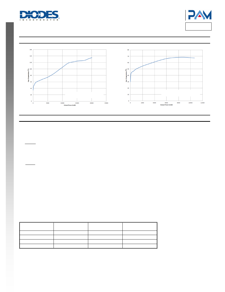
Performance Characteristics
(@T
A
= +25°C, V
CC
= 24V, f = 1kHz, Gain = 20dB unless otherwise specified.)
Case Temperature vs. Output Power (R
L
= 4Ω)
Case Temperature vs. Output Power (R
L
= 8Ω)
Application Information
Input Capacitors (Ci)
In the typical application, an input capacitor Ci, is required to allow the amplifier to bias the input signal to the proper DC level for optimum
operation. In this case, Ci and the minimum input impedance Ri form is a high-pass filter with the corner frequency determined in the follow
equation:
(
)
C
1
f
2 RiCi
π
=
It is important to consider the value of Ci as it directly affects the low frequency performance of the circuit. For example, when Ri is 40kΩ and the
specification calls for a flat bass response are down to 20Hz. Equation is reconfigured as followed:
(
)
i c
1
Ci
2 R f
π
=
When input resistance variation is considered Ci is 200nF, so one would likely choose a value of 220nF. A further consideration for this capacitor
is the leakage path from the input source through the input network (Ci, Ri + Rf) to the load. This leakage current creates a DC offset voltage at
the input to the amplifier that reduces useful headroom, especially in high gain applications. For this reason, a low-leakage tantalum or ceramic
capacitor is the best choice.
Gain Setting Control
The gain of the PAM8124 is set by two input terminals, GAIN0 and GAIN1.
The gains listed in following table are realized by changing the taps on the input resistors inside the amplifier. This causes the input impedance to
be dependent on the gain setting. The actual gain settings are controlled by ratios of resistors, so the gain variation from part-to-part is small.
However, the input impedance from part-to-part at the same gain may shift by ±20% due to shifts in the actual resistance of the input resistors.
Table 1: Gain Setting
Gain1 Gain0
Amplifier Gain (dB),
Typical
Input Impedance (kΩ),
Typical (Ri)
0 0 20
40
0 1 26
20
1 0 30
10
1 1 36
6.67
Two Channels Driving
Two Channels Driving