Functional descriptions, Am4964 – Diodes AM4964 User Manual
Page 7
AM4964
Document number: DS37241 Rev. 2 - 2
7 of 21
June 2014
© Diodes Incorporated
AM4964
A Product Line of
Diodes Incorporated
N
E
W
P
R
O
D
U
C
T
Functional Descriptions
HB
– Hall Bias Output
This is a 1.25V nominal voltage source to bias a differential un-buffered Hall element sensor. If a Hall element requires a lower voltage than the
H-Bias output, connect an appropriate value resistor between the HB pin and the Hall element supply pin.
IN+ and IN-
– Hall Inputs
The rotor position is detected by a Hall sensor, with the output applied to the IN+ and IN- pins. This sensor can be either a 4 pin 'naked' Hall
device or of the 3-pin buffered switching type. For a 4-pin device the differential Hall output signal is connected to the IN+ and IN-pins. For a
buffered Hall sensor the Hall device output is attached to the IN+ pin, with a pull-up attached if needed, whilst the IN- pin has an external
potential divider attached to hold the pin at half V
REF
. When IN+ is high in relation to IN-, OUT2 is the active drive.
PWM
– Pulse Width Modulate Signal Input Pin
The PWM signal is applied at this pin and then be translated to be stable voltage to control the motors rotate speed.
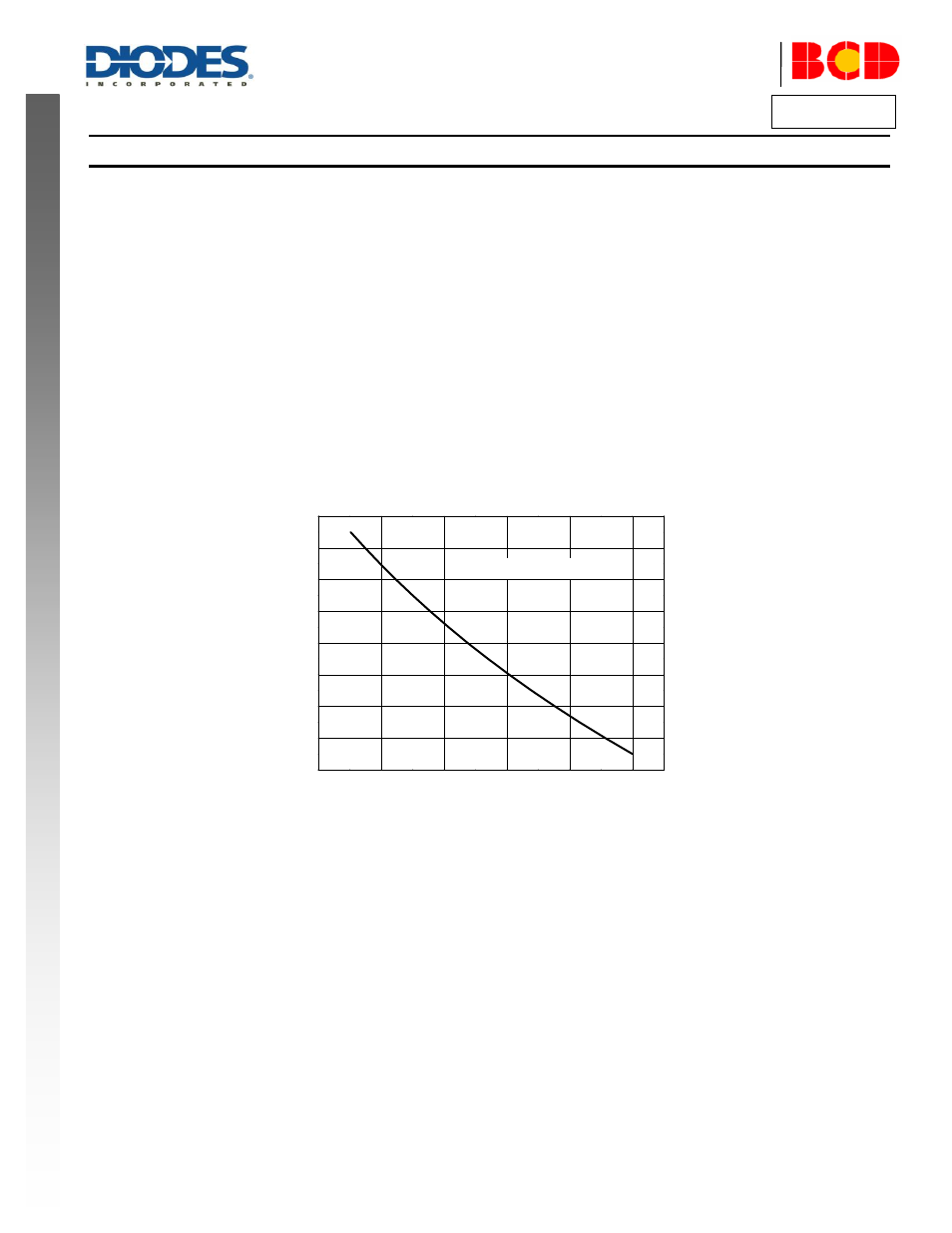
TL
– Low Temperature Corner Set Pin
A resistor (R8) is connected between TL and ground to adjust the low corner temperature.
Low Temperature Corner Value vs. R8 Resistor Value
5
6
7
8
9
10
24
26
28
30
32
34
36
38
40
L
o
w
C
o
rn
e
r
T
e
mp
e
ra
tu
re
(
o
C)
R8 (k
)
R
T
=TSM2A103F39H1RZ