Functional descriptions, Am4964 – Diodes AM4964 User Manual
Page 11
AM4964
Document number: DS37241 Rev. 2 - 2
11 of 21
June 2014
© Diodes Incorporated
AM4964
A Product Line of
Diodes Incorporated
N
E
W
P
R
O
D
U
C
T
Functional Descriptions
(cont.)
CT
– Locked Rotor Timing Capacitor
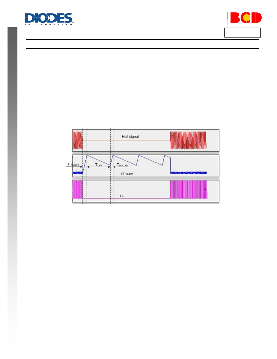
The CT pin will have a capacitor connected to ground. It is a multi-function pin providing timing for the lock detect and auto-restart. Different
rates of charge and discharge of CT capacitor depending on the mode of operation (fan operation status) give the lock-detect time (t
LCKDET
)
and
lock time (t
OFF
) before the next auto-start retry. When the motor is running, the capacitor is discharged at every Hall signal change.
CT pin provides the timing for the Locked Rotor monitor. In normal operation, Lock Detect is enabled. If the Hall signal does not change (i.e. a
rotor lock condition) within the Lock Detect time (t
LCKDET
), the outputs are disabled. In this condition the motor will not be driven for a set time t
OFF
.
This t
OFF
time depends on the external CT capacitor value and its internal discharge current (I
DHG
). After the t
OFF
period device enters auto-restart
phase to re-start the motor with a new Lock Detect time. If the motor has not turned to generate a transition on the Hall inputs by the end of this
t
LCKDET
period, the motor re-enters motor lock t
OFF
period with the outputs disabled. If the Hall signal change is detected, the motor is deemed as
running and goes into lock-detection mode. The t
LCKDET
and t
OFF
are determined by the value of the external capacitor on the CT pin and the
internal charge and discharge currents during these time periods. The currents during t
LCKDET
and t
OFF
are I
CHG
, and I
DHG
respectively.
FG
– Frequency Generator (Tachometer) Output Pin
This is the Frequency Generator output and is a buffered signal from the Hall sensor. This is an open collector drive giving an active pull down
with the high level being provided by an external pull up resistor.
OUT1 and OUT2 Pins
OUT1 and OUT2 pins provide H bridge driver output for fan and motor coil connection.
VCC
– IC Supply voltage
This pin provides the supply for the device.
GND
– Supply Return
This is the device supply ground return pin for control signal.
PGND
–Power Supply Return
This is the device supply ground return pin for power output pins OUT1 and OUT2 and will generally be the most negative supply pin to the fan.