Functional descriptions, Am4964, A product line of diodes incorporated – Diodes AM4964 User Manual
Page 10
AM4964
Document number: DS37241 Rev. 2 - 2
10 of 21
June 2014
© Diodes Incorporated
AM4964
A Product Line of
Diodes Incorporated
N
E
W
P
R
O
D
U
C
T
Functional Descriptions
(cont.)
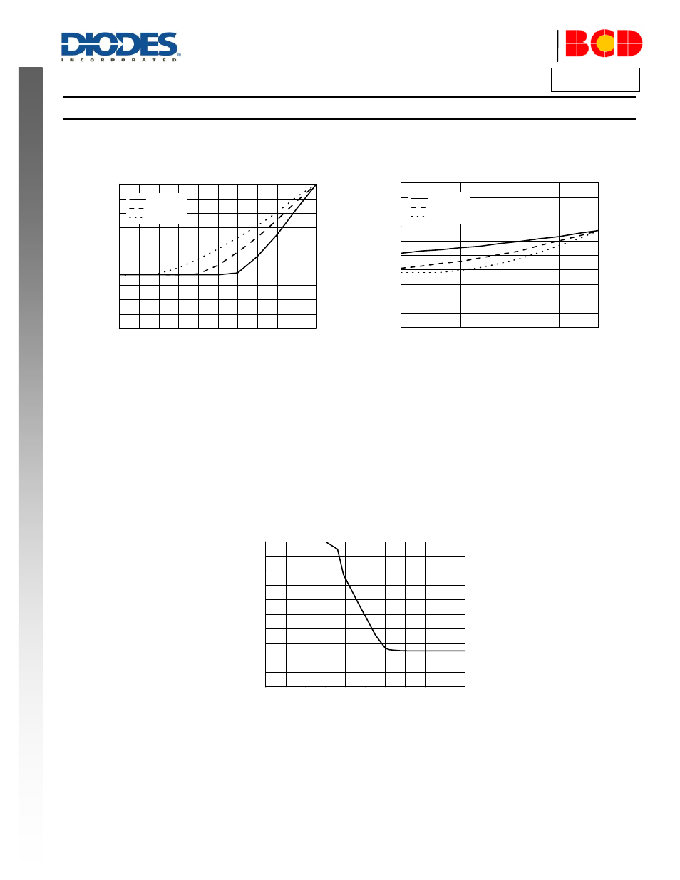
RADJ
– Adjust the Line Slope of the Input PWM Duty vs. Output PWM Duty at the OUT1 and OUT2
Adjust Slope K of the fan rotating speed
(or output duty)vs. input duty to approximately match the target specification using R5 and R6.
Output PWM Duty Slope K vs. Input PWM Duty with Slope K R5 and R6
VMIN
– Minimum Speed Setting
A voltage can be set on this pin via a potential divider between the VREF (or Supply) and GND pins. This voltage is monitored by the PWM pin
to clamp the PWM control voltage so that it does not rise above VMIN voltage. As a higher voltage on the PWM pin represents a lower speed,
the VMIN setting prevents the motor speed going lower than the minimum speed set by the VMIN pin. When the VMIN voltage is higher than the
lowest speed setting voltage allowed (The lowest speed voltage is about 0.28V
CC
), the fan speed is maintained at the lowest speed.
Adjust the minimum speed vs. input duty to approximately match the target specification via R2 (R1=15k
Ω). Measure the fan rotating speed and
the input duty, as shown below.
0
1
2
3
4
5
6
7
8
9
10
0
20
40
60
80
100
O
u
tp
u
t
D
u
ty
C
ycl
e
(%
)
R2 (K
)
Output PWM Duty vs. R2
0
10
20
30
40
50
60
70
80
90
100
0
20
40
60
80
100
R5=100K
R5=270K
R5 is open
O
u
tp
u
t
D
u
ty
C
ycl
e
(%
)
Input Duty (%)
0
20
40
60
80
100
0
20
40
60
80
100
R6=100K
R6=270K
R6 open
O
u
tp
u
t
D
u
ty
(%
)
Input Duty (%)