Diodes AM4964 User Manual
Am4964, Description, Features
AM4964
Document number: DS37241 Rev. 2 - 2
1 of 21
June 2014
© Diodes Incorporated
AM4964
A Product Line of
Diodes Incorporated
N
E
W
P
R
O
D
U
C
T
SINGLE PHASE FULL WAVE DIRECT PWM MOTOR DRIVER
Description
The AM4964 is highly integrated feature rich single phase Brushless
Direct Current (BLDC) full wave motor driver with combined PWM and
temperature speed control function for fans, blowers and extractors.
For system flexibility, the motor speed can be controlled by an
external PWM signal and temperature sensed by Thermal resister at
the same time. Based on external input PWM and temperature
signals, the AM4964 adjusts the output PWM duty cycle. If the input
PWM duty is constant, the output PWM duty varies with temperature
sensed by Thermal resister sensor between the low and high
temperature corners. If the temperature signal is constant, the output
duty varies with the external input PWM duty. The low and high
temperature corners and the output PWM duty gap between these
temperature corners are adjustable
To help protect the motor coil, the AM4964 provides a rotor lock
protection which shuts down the output if rotor lock is detected. The
device automatically re-starts when the rotor lock is removed.
AM4964 provides a tachometer outpu
t Frequency Generator
(FG). The FG output is the magnetic change frequency.
The AM4964 is available in TSSOP-20EP package.
Features
Flexible Speed Control Options
Combined PWM+Thermistor Speed Control
PWM Speed Control
DC Voltage Speed Control
Adjustable Low and High Temperature Corners
Full Speed When Thermal Resistor is Shorted
Adjustable Output Duty Gap between High and Low
Temperature when 100% PWM Input
Built-in oscillator
– No external capacitor
Built-in Minimal Speed Setup Circuit
Alpha Slope Adjustable
Rotation Speed Indicator (FG)
Built-in Temperature Control Circuit
Built-in Thermal Shutdown Circuit
Lock Protection and Auto-restart
Totally Lead-free & Fully RoHS Compliant (Notes 1 & 2)
Halogen and Antimony Free.
“Green” Device (Note 3)
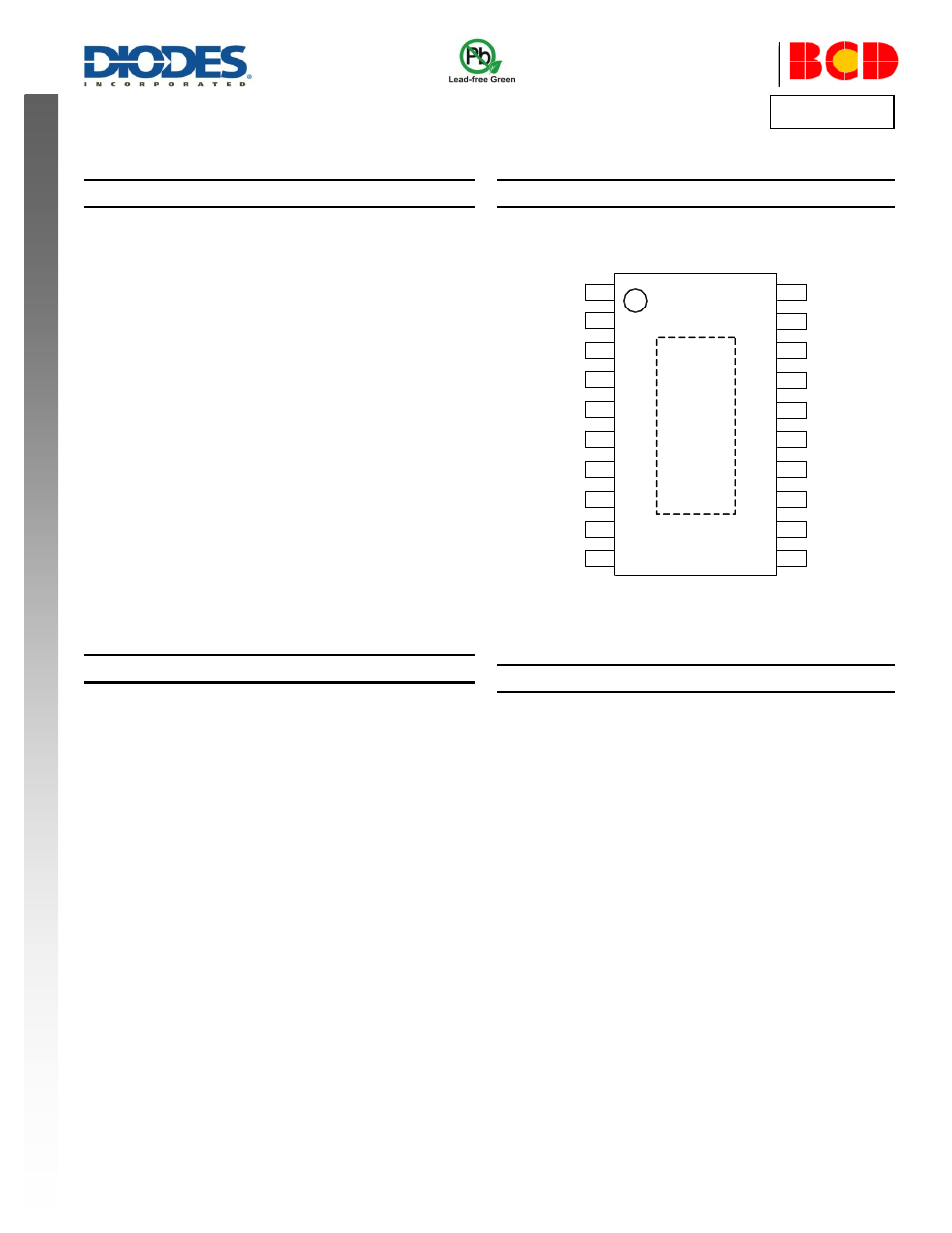
Pin Assignments
(Top View)
NC
PGND
OUT2
VCC
VMIN
PWM
CF
FG
RT
TL
IN+
HB
IN-
RADJ
CT
SGND
TH
TA
OUT1
NC
1
2
3
4
5
6
7
8
9
10
20
19
18
17
16
15
14
13
12
11
E
X
P
O
S
E
D
P
A
D
TSSOP-20EP
Applications
CPU Cooler Fan in PC
Brushless DC Motor Driver
Notes:
1. No purposely added lead. Fully EU Directive 2002/95/EC (RoHS) & 2011/65/EU (RoHS 2) compliant.
2. See
r more information about Diodes Incorporated’s definitions of Halogen- and Antimony-free, "Green"
and Lead-free.
3. Halogen- and Antimony-
free "Green” products are defined as those which contain <900ppm bromine, <900ppm chlorine (<1500ppm total Br + Cl) and
<1000ppm antimony compounds.