Am4964 – Diodes AM4964 User Manual
Page 15
AM4964
Document number: DS37241 Rev. 2 - 2
15 of 21
June 2014
© Diodes Incorporated
AM4964
A Product Line of
Diodes Incorporated
N
E
W
P
R
O
D
U
C
T
Applications Note
(cont.)
Power Supply Stabilization
The recommended operating voltage range for AM4964 is 3.5V to 16V. A decoupling capacitor C1 (which also acts as re-circulating capacitor at
commutation) should be connected close to the VCC pin. C1 is for power stabilization and should be 1
μF or higher depending on the motor
current and motor design.
Hall Bias and Hall Input for Commutation Signal
The HB pin provides a 1.25V Hall bias voltage to drive Hall element. The output of the Hall elements or the Hall switches
is connected to Hall
input IN+ and IN- pin as described previously in functional description section. To avoid noise, the connection to the Hall element or switch
should be as short as possible. The Hall input stage (IN+ and IN- pin) has a hysteresis of 20mV typical. The differential Hall input signal should
be
50mV peak or
higher.
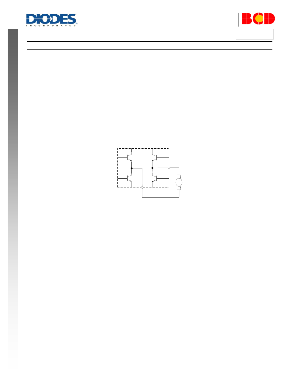
Speed Control
The motor speed is governed by the output PWM duty of the H Bridge.
Speed Control
The motor speed is governed by the output PWM duty of the H Bridge.
M
The voltage on the CF, VMIN pin and
the internal triangle wave voltage controls the output PWM duty and therefore the speed of the motor.
When the CF voltage is smaller than VMIN voltage, the output PWM duty is generated by comparing the triangular voltage with CF. If the CF pin
voltage is higher than the VMIN pin, the speed is controlled by comparing the triangular voltage with VMIN voltage. When the PWM voltage is
lower than the low side of the triangular voltage
, the motor will run at full speed. See “Speed Control and Minimum Speed Setting” figure.
An input DC voltage from 3.6V to 1.9V (for 12V supply) on the CF pin controls the output PWM duty from 0% to 100%
thus allowing speed
control from 0% to 100% of the full speed. The DC voltage of CF can be adjusted by PWM input signal duty and the ambient temperature
sensed by the thermistor (resistive sensor) connected to RT pin.