Ah5792, Typical application circuit, Pin descriptions – Diodes AH5792 User Manual
Page 2
AH5792
SINGLE PHASE HALL EFFECT LATCH SMART
FAN MOTOR CONTROLLER
AH5792
Document number: DS314641 Rev. 6 - 2
2 of 10
July 2010
© Diodes Incorporated
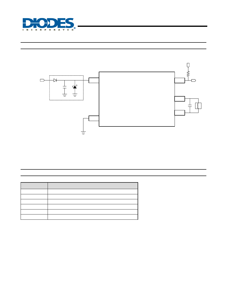
Typical Application Circuit
(Note 1)
V
dd
FG
O1
O2
FG
SYSTEM
POWER
V
SS
SYSTEM
POWER
10Kohm
AH5792
Dz
C1
D1
Notes: 1. Reverse connection of power supply may break the device. A countermeasure is needed such as using reverse power protection
diode D1 between power supply and Vdd terminal. In such case of using reverse power protection diode D1 because of there is no
way to return current to power supply, please take necessary measures like below.
- Connect Dz (Zener diode) between Vdd and Vss terminal, not to exceed the absolute maximum rating voltage.
- Connect a capacitor C1 between Vdd and Vss terminal, to make the path of return current to power supply.
The AH5792 has an open-drain tachometer FG output that follows the half (1/2) the magnetic change frequency. A pull-up resistor
(10Kohm, typically for System Power = 5V) connected to a supply voltage.
Pin Descriptions
(Note 2)
Pin Name
Description
O1
Output driving & sinking pin 1
Vdd
Power supply pin
Vss Ground
pin
FG
Frequency Generator (Note 2)
O2
Output driving & sinking Pin 2
NC No
Connection
Notes: 2. The FG is half (1/2) the magnetic change frequency.