Data sheet, Digital dimming operating diagram – Diodes AP3606/AP3607 User Manual
Page 14
Data Sheet
4/6 CHANNEL CHARGE PUMP CURRENT SINK FOR LED DRIVER AP3606/AP3607
Jan. 2013 Rev. 1. 5 BCD Semiconductor Manufacturing Limited
14
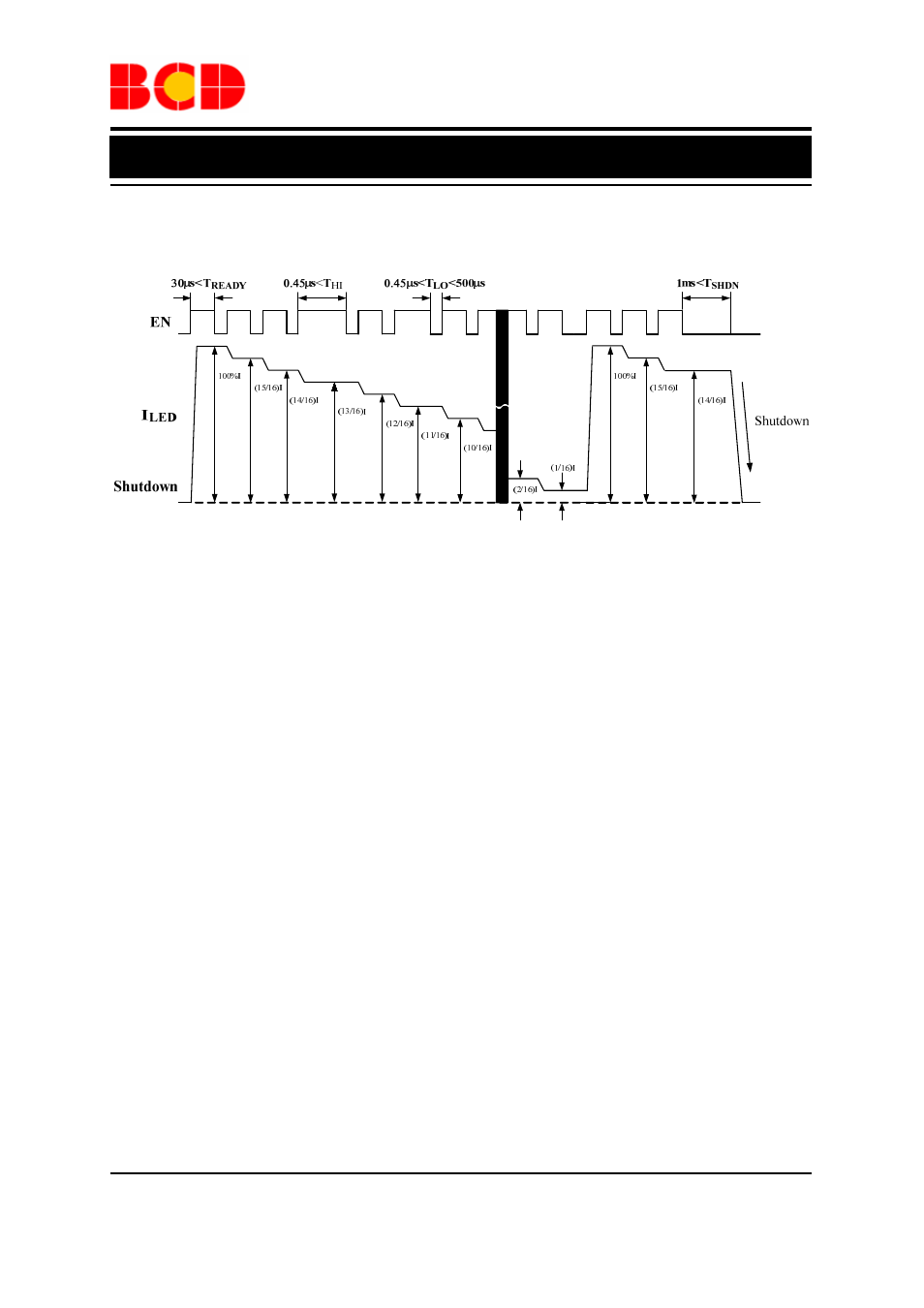
Digital Dimming Operating Diagram
Figure 32. Digital Dimming Operating Diagram of AP3606/AP3607
Note 3: The dimming control can be achieved by applying a pulse to the EN pin. When the low level duration
time of pulse is between T
LOmin
and T
LOmax
, and the high level duration time is larger than T
HImin
, the LED current
will decrease 1/16. If the low level duration time is larger than T
SHDNmax,
the IC will be turned off. When
AP3606/AP3607 is powered on, the WLED is in full brightness. And it will keep maximum current until the
pulse is detected. After 15 pulses the WLED current decreases to 1/16 of full brightness. It will increase to full
brightness if a pulse is added to EN pin then.
- PDS3200 (5 pages)
- PDS340 (5 pages)
- PDS340Q (5 pages)
- PDS360 (5 pages)
- PDS360Q (5 pages)
- PDS4150 (4 pages)
- PDS3100Q (5 pages)
- PDS3100 (5 pages)
- PDS1240CTL (5 pages)
- PDS1045 (5 pages)
- PDS1040L (5 pages)
- PDS1040CTL (5 pages)
- PDS1040 (5 pages)
- PD3S230L (5 pages)
- PD3S230H (3 pages)
- PDS5100Q (5 pages)
- PDS835L (5 pages)
- PDS760 (5 pages)
- PDS560 (5 pages)
- PDS540 (5 pages)
- PDS5100H (5 pages)
- PDS5100 (5 pages)
- PDS4200H (6 pages)
- SBL3060CTP (4 pages)
- SBL30L30CT (3 pages)
- SBL3045CTP (4 pages)
- SBL3040CTP (4 pages)
- SBL2060CTP (4 pages)
- SBL2030CT - SBL2060CT (3 pages)
- SBL2045CTP (4 pages)
- SBL1060CTP (4 pages)
- SBL1040CTP (4 pages)
- SBG3030CT - SBG3045CT (5 pages)
- SB520 - SB560 (3 pages)
- SB370 - SB3100 (3 pages)
- SB320 - SB360 (3 pages)
- SBR10U100CT (5 pages)
- SBR10U150CT (5 pages)
- SBR10A45SP5 (5 pages)
- SBR1060CT (5 pages)
- SBR1045SP5 (5 pages)
- SBR1045SD1 (4 pages)
- SBR1045D1 (5 pages)
- SBR1045CTL (4 pages)
- SBR1040CT (5 pages)