Ap8800a, Application information – Diodes AP8800A User Manual
Page 8
AP8800A
Document number: DS35100 Rev. 3 - 2
8 of 13
August 2012
© Diodes Incorporated
AP8800A
Application Information
(cont.)
(@T
A
= +25°C, V
IN
= 12V, unless otherwise specified.)
LED Current Dimming
The LED current can be dimmed in two ways;
1.
Analog Dimming: Where a dc voltage is applied to the CTRL pin
or
2.
PWM Dimming: Where a Pulse Width Modulated (PWM) signal is applied to the CTRL pin.
Analog Dimming
If the CTRL pin is driven by an external voltage (lower than 2.5V), the average LED current in this case is:
SET
TH
REF
CTRL
LED
R
V
V
V
I
×
=
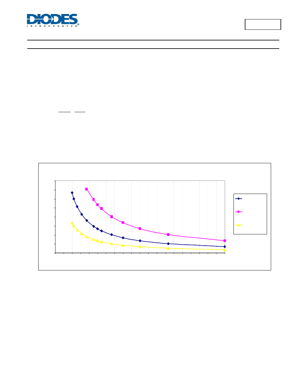
A DC signal from 0.3V to 2.5V applied to the CTRL pin will vary the LED current from 24% to 200% of nominal LED current. This gives an
approximate 8:1 dimming range; care, should be exercised when overdriving the CTRL pin to 200% of nominal LED current not to exceed the
power dissipation of the package.
The graph in figure 4 shows values of nominal average output current for 3 values of current setting resistor (R
SET
) in the typical application
circuit shown on Figure 1, for different voltages applied on the CTRL pin.
LED current Versus RSET and VCTRL
0.3
0.33
0.39
0.47
0.56
3
0.56
0.68
0.75
0.82
1
1.2
3
0.3
0.39
0.47
0.56
0.68
0.82
1
1.2
1.5
2
3
1.2
1
0.82
0.68
1.5
2
1.5
2
0
50
100
150
200
250
300
350
400
0
0.15 0.3 0.45 0.6 0.75 0.9 1.05 1.2 1.35 1.5 1.65 1.8 1.95 2.1 2.25 2.4 2.55 2.7 2.85
3
RSET value [Ohms]
L
E
D C
u
rr
e
n
t
[m
A]
LED current @
VCTRL = 1.25V
LED current @
VCTRL = 2.5V
LED current @
VCTRL = 0.625V
Figure 4 LED Current Setting vs. R
SET
and V
CTRL