Application information, Ap8800a, Fault conditions – Diodes AP8800A User Manual
Page 10
AP8800A
Document number: DS35100 Rev. 3 - 2
10 of 13
August 2012
© Diodes Incorporated
AP8800A
Application Information
(cont.)
(@T
A
= +25°C, V
IN
= 12V, unless otherwise specified.)
Fault Conditions
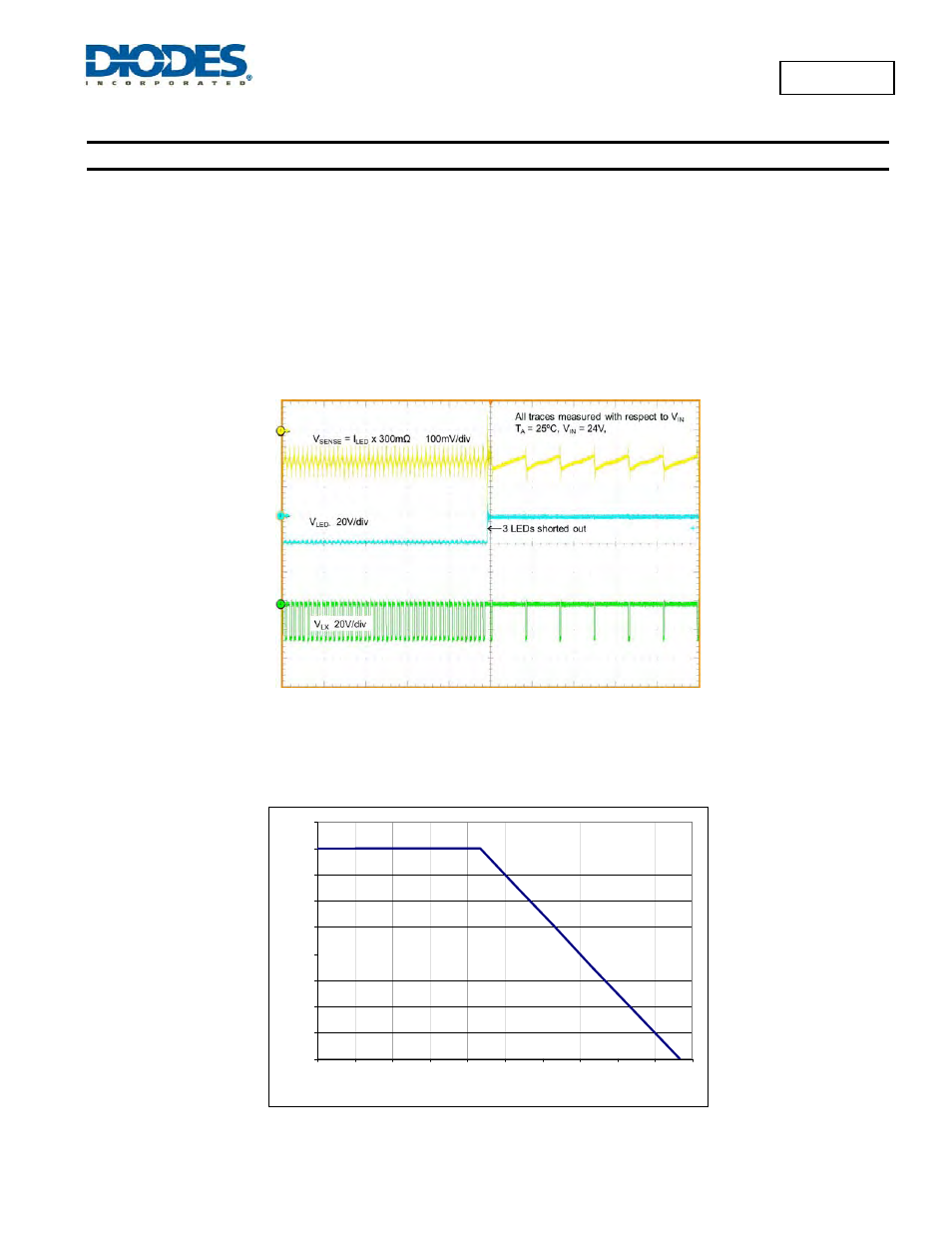
The AP8800A is inherently protected against open-LED conditions. If one LED becomes open circuit the device automatically stops switching
and will only retart if the open-LED fault is removed.
If one or more LEDs should become shorted together then the switching frequency and duty cycle will change. If one or more LEDs get shorted
together, the ramp-up time of LED current will become shorter due to there being a larger voltage across the inductor. However, the ramp-down
time of the LED current will increase due to the voltage across the inductor becoming smaller.
Figure 7 below shows the AP8800A driving 3 LEDs when all 3 LEDs become shorted together. Due to the large voltage change across the
inductor during both LED current ramp-up and ramp-down we see a large difference in switching frequency.
Figure 7 LED Short Fault Condition
Thermal Considerations
The graph below in Figure 8, gives details for the power derating of the AP8800AWT. This assumes the device to be mounted on a 25 x 25mm
PCB with 1oz copper standing in still air.
0
50
100
150
200
250
300
350
400
450
-40
-25
-10
5
20
35
50
65
80
95
110
Ambient temperature (°C)
P
o
w
e
r d
iss
ip
ati
o
n
(m
W
)
Figure 8 Derating Curve