Ap7362, Application information – Diodes AP7362 User Manual
Page 8
AP7362
Document number: DS35058 Rev. 6 - 2
8 of 15
August 2013
© Diodes Incorporated
AP7362
Application Information
Input Capacitor
A minimum 2.2μF ceramic capacitor is recommended between IN and GND pins to decouple input power supply glitch and noise. The amount of
the capacitance may be increased without limit. Larger input capacitor like 10μF will provide better load transient response. This input capacitor
must be located as close as possible to the device to assure input stability and reduce noise. For PCB layout, a wide copper trace is required for
both IN and GND pins. A lower ESR capacitor type allows the use of less capacitance, while higher ESR type requires more capacitance.
Output Capacitor
The output capacitor is required to stabilize and help the transient response of the LDO. The AP7362 is stable with any type of capacitor, with no
limitations on minimum or maximum ESR. The device is designed to have excellent transient response for most applications with a small amount
of output capacitance. The device is also stable with multiple capacitors in parallel, which can be of any type of value. Additional capacitance
helps to reduce undershoot and overshoot during transient loads. This capacitor should be placed as close as possible to OUT and GND pins for
optimum performance.
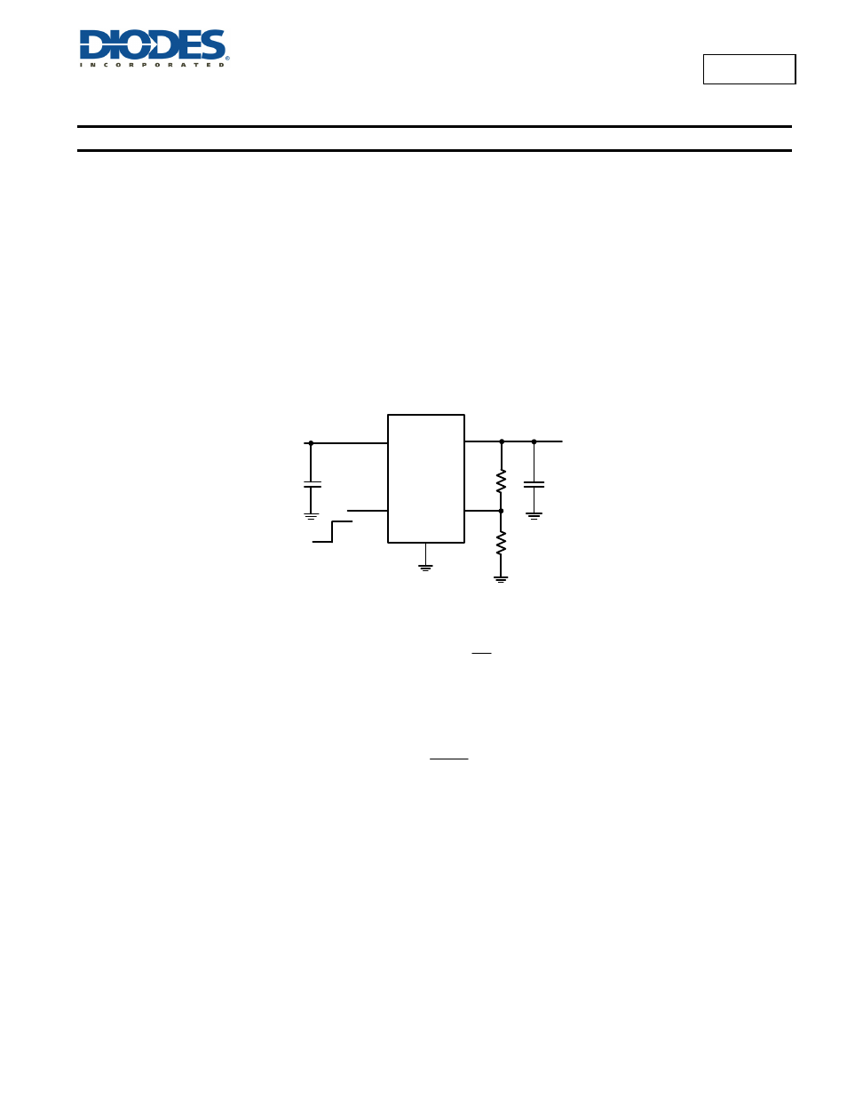
Adjustable Operation
The AP7362 provides output voltage from 0.6V to 5.0V through external resistor divider as shown below.
The output voltage is calculated by:
2
R
1
R
1
REF
V
OUT
V
Where V
REF
= 0.6V (the internal reference voltage)
Rearranging the equation will give the following that is used for adjusting the output to a particular voltage:
1
REF
V
OUT
V
2
R
1
R
To maintain the stability of the internal reference voltage, R
2
need to be kept smaller than
10k
.
No Load Stability
Other than external resistor divider, no minimum load is required to keep the device stable. The device will remain stable and regulated in no
load condition.
10µF
IN
GND
EN
OUT
Enable
ADJ
R2
R1
10µF
V
IN
V
OUT
AP7362
Adjustable Output