Ap7115, 150ma low dropout linear regulator with shutdown – Diodes AP7115 User Manual
Page 8
AP7115
150mA LOW DROPOUT LINEAR REGULATOR WITH
SHUTDOWN
AP7115 Rev. 10
8 of 11
MAY 2009
©
Diodes Incorporated
Application Note
Input Capacitor
An 1uF input capacitor is required between the AP7115 input pin
and GND.
There are no requirements for the ESR on input capacitor, but
tolerance and temperature coefficient must be considered.
Output Capacitor
The AP7115 can work with very small ceramic output capacitors
(1uF or greater). Higher capacitance values help to improve
transient. The output capacitor’s ESR is critical because it from a
zero to provide phase lead which is required for loop stability.
Figure below is Cout ESR vs. Load Current.
Band-Gap Bypass Capacitor
0.1uF bypass capacitor Between BP pin and GND can reduces
output voltage noise.
Shutdown Input Operation
The AP7115 is shutdown by pulling the EN pin low, and turned on
by driving the input high. If the shutdown feature is not required,
the EN pin should be tied to VIN to keep the regulator on at all
times.
Dropout Voltage
V
DROPOUT
=V
IN
-V
OUT
=R
DS(ON)
×I
OUT
Current Limit
The AP7115 monitors and controls the PMOS’ gate voltage,
limiting the output current to 250mA(typ.). The output can be
shorted to ground for an indefinite period of time without
damaging the part.
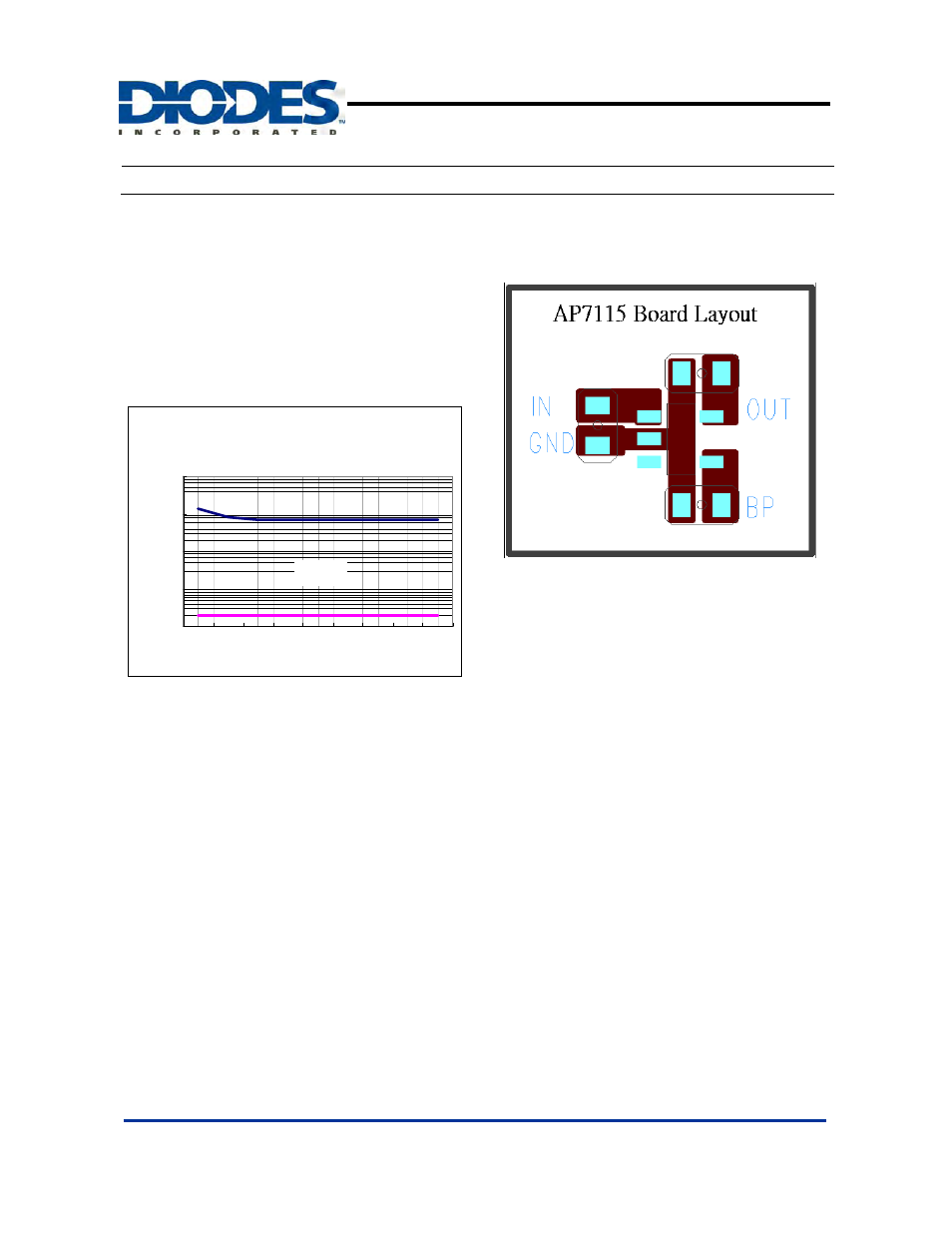
PCB Layout
Optimum performance can only be achieved when the device is
mounted on a PC board according to the diagram below:
Thermal Considerations
Thermal Shutdown Protection limits power dissipation in AP7115.
When the operation junction temperature exceeds 155°C, the
Over Temperature Protection circuit starts the thermal shutdown
function and turns the pass element off. The pass element turn
on again after the junction temperature cools by 30°C. For
continuous operation, do not exceed absolute maximum
operation junction temperature 125°C. The power dissipation
definition in device is:
P
D
= (V
IN
− V
OUT
) x I
OUT
+ V
IN
x I
Q
The maximum power dissipation depends on the thermal
resistance of IC package, PCB layout, the rate of surroundings
airflow and temperature difference between junction to ambient.
The maximum power dissipation can be calculated by the
following formula:
P
D(MAX)
= ( T
J(MAX)
- T
A
) /
θ
JA
Where T
J(MAX)
is the maximum operation junction temperature
125°C, T
A
is the ambient temperature and the
θ
JA
is the junction
to ambient thermal resistance.
AP7115 Region of Stable Cout ESR vs.
Load Current
0.01
0.1
1
10
100
0
20
40
60
80
100
120
140
160
Load Current (mA)
C
out
E
S
R
(
Ω
)
Stable