Diodes AP2552/ AP2553/ AP2552A/ AP2553A User Manual
Page 10
AP2552/AP2553/AP2552A/AP2553A
Document number: DS35404 Rev. 8 - 2
10 of 16
February 2014
© Diodes Incorporated
AP2552/ AP2553/ AP2552A/ AP2553A
Application Note
(cont.)
Current-Limit Threshold Programming
The current-limit threshold can be programmed using an external resistor. The current-limit threshold is proportional to the current sourced out of
I
LIM
.
The recommended 1% resistor range for R
LIM
is 10kΩ ≤R
LIM
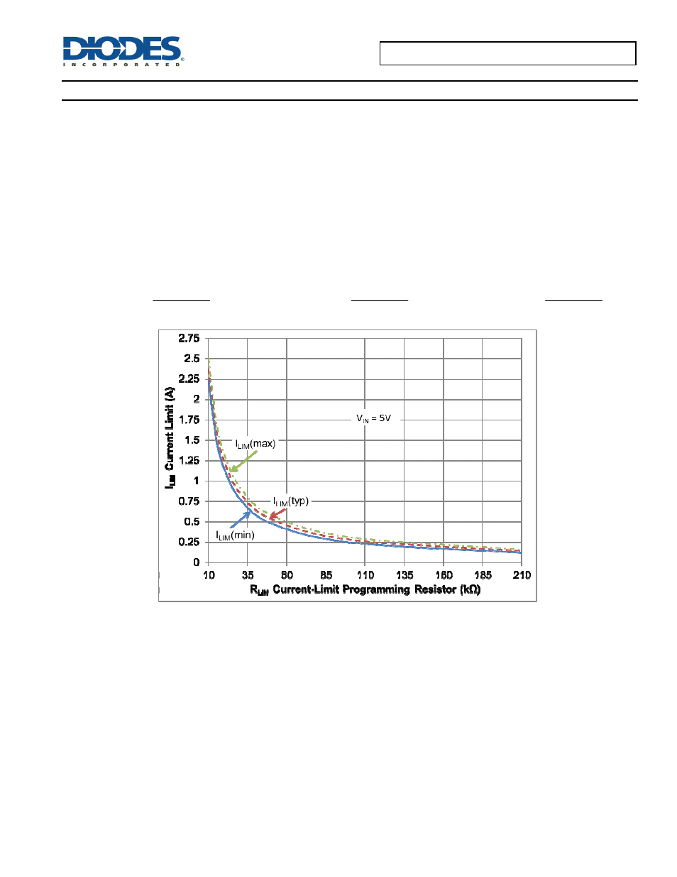
≤210kΩ. Figure 15 includes current-limit tolerance due to variations caused by
temperature and process. This graph does not include the external resistor tolerance. The traces routing the RLIM resistor to the AP2552/53 and
AP2552A/53A should be as short as possible to reduce parasitic effects on the current-limit accuracy.
To design below a maximum current-limit threshold, find the intersection of R
LIM
and the maximum desired load current on the I
OS(max)
(I
LIM
)
curve and choose a value of R
LIM
above this value. Programming the current limit below a maximum threshold is important to avoid current
limiting upstream power supplies causing the input voltage bus to droop. The resulting minimum current-limit threshold is the intersection of the
selected value of R
LIM
and the I
OS(min)
(I
LIM
) curve.
Best fit Current-Limit Threshold Equations (I
LIMIT
):
k
08
.
20
)
A
(
I
904
.
0
LIM
)
MAX
(
LIM
R
k
94
.
19
)
mA
(
I
925
.
0
LIM
)
TYP
(
LIM
R
k
26
.
20
)
mA
(
I
956
.
0
LIM
)
MIN
(
LIM
R
Figure 15 Current-Limit Threshold vs. R
LIM
Thermal Protection
Thermal protection prevents the IC from damage when the die temperature exceeds safe margins. This mainly occurs when heavy-overload or
short-circuit faults are present for extended periods of time. The AP2552/53 AND AP2552A/53A implements a thermal sensing to monitor the
operating junction temperature of the power distribution switch. Once the die temperature rises to approximately +160°C (140°C in case the part
is under current limit), the thermal protection feature gets activated as follows: The internal thermal sense circuitry turns the power switch off and
the FAULT output is asserted thus preventing the power switch from damage. Hysteresis in the thermal sense circuit allows the device to cool
down by approximately +20°C before the output is turned back on. This built-in thermal hysteresis feature is an excellent feature, as it avoids
undesirable oscillations of the thermal protection circuit. The switch continues to cycle in this manner until the load fault is removed, resulting in
a pulsed output.