Ap3417c preliminary datasheet, Recommended operating conditions, Electrical characteristics – Diodes AP3417C User Manual
Page 4
AP3417C
Document number: DS36516 Rev. 1 - 0
4 of 11
www.diodes.com
September 2013
© Diodes Incorporated
AP3417C
PRELIMINARY DATASHEET
A Product Line of
Diodes Incorporated
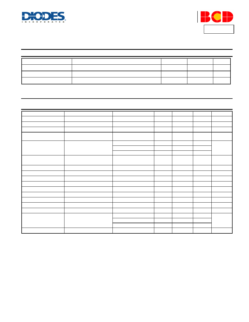
Recommended Operating Conditions
Symbol Parameter
Min
Max
Unit
V
IN
Supply Input Voltage
2.5
5.5
V
T
A
Operating Ambient Temperature
-40
85
ºC
T
J
Operating Junction Temperature
-40
125
ºC
Electrical Characteristics
(@V
IN
= V
EN
= 5V, V
OUT
= 1.2V, V
FB
= 0.6V, L = 2.2µH, C
IN
= 4.7µF, C
OUT
= 10µF, T
A
= +25°C, unless
otherwise specified.)
Symbol Parameters
Conditions
Min
Typ
Max
Unit
V
IN
Input Voltage Range
2.5
5.5
V
I
OFF
Shutdown Current
V
EN
= 0
0.1
µA
I
ON
Active Current
V
FB
= 0.55V
220 µA
V
FB
Regulated Feedback Voltage
For Adjustable Output
Voltage
0.588 0.6 0.612 V
V
OUT
Output Voltage
Fixed Output 1.2V
1.176
1.2
1.224
V
Fixed Output 1.8V
1.764
1.8
1.836
Fixed Output 3.3V
3.234
3.3
3.366
V
OUT
/V
OUT
Regulated Output Voltage
Accuracy
V
IN
= 2.5V to 5.5V,
I
OUT
= 0 to 1.0A
-3 3 %
I
PK
Peak Inductor Current
1.5
1.9
A
f
OSC
Oscillator Frequency
V
IN
= 2.5V to 5.5V
1.2 1.5 1.8 MHz
R
DS(ON)P
PMOSFET
R
DS(ON)
V
IN
= 5V
200 m
R
DS(ON)N
NMOSFET
R
DS(ON)
V
IN
= 5V
200 m
V
EN_H
EN High Level Input Voltage
1.5
V
V
EN_L
EN Low Level Input Voltage
0.4
V
I
EN
EN Input Current
0.1
µA
t
SS
Soft Start Time
400
µs
D
MAX
Maximum Duty Cycle
100
%
V
UVLO
Under Voltage Lock Out
Threshold
Rising
2.3
V
Falling
2.1
Hysteresis
0.2
T
SD
Thermal Shutdown
Hysteresis = 30°C
155
160
°C