Al5801, Pwm dimming – Diodes AL5801 User Manual
Page 9
AL5801
Document number: DS35555 Rev. 3 - 2
9 of 11
July 2012
© Diodes Incorporated
AL5801
PWM Dimming
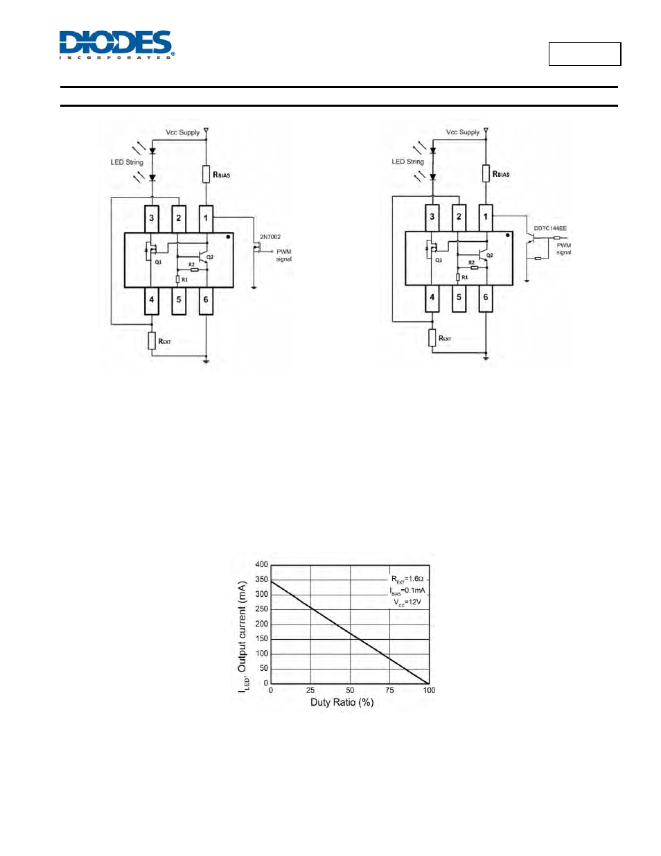
(a)
(b)
Figure 16 Application Circuits for LED Driver with PWM Dimming Functionality (a) MOSFET driving and (b) Transistor driving
PWM dimming can be achieved by driving the BIAS pin (1). An external open-collector NPN transistor or open-drain N-channel MOSFET can be
used to drive the BIAS pin as shown in Figure 16. Dimming is achieved by turning the LEDs ON and OFF for a portion of a single cycle. The
PWM signal can be provided by a micro-controller or by analog circuitry.
Figure 17 shows the LED current against the PWM signal duty ratio when the AL5801 is used to drive three series connected LEDs from a 12V
supply. The PWM dimming frequency is set to 200Hz. The PWM signal is supplied to the open-Drain small signal MOSFET’s gate as shown in
Figure 16a. The BIAS pin signal is an inversion of the PWM drive to the MOSFET’s gate. Therefore, a PWM signal duty cycle of 0% provides the
maximum LED current. Sufficiently large PCB copper area is used for heat sinking of the AL5801 in order to minimize the device self-heating at
+25
°C
ambient.
Figure 17 LED Current against PWM Dimming Signal Duty Ratio at 200Hz PWM Frequency