Zxre160 new prod uc t, Application information – Diodes ZXRE160 User Manual
Page 9
ZXRE160
Document number: DS35688 Rev. 2 - 2
9 of 15
June 2012
© Diodes Incorporated
ZXRE160
NEW PROD
UC
T
A Product Line of
Diodes Incorporated
Application Information
(cont.)
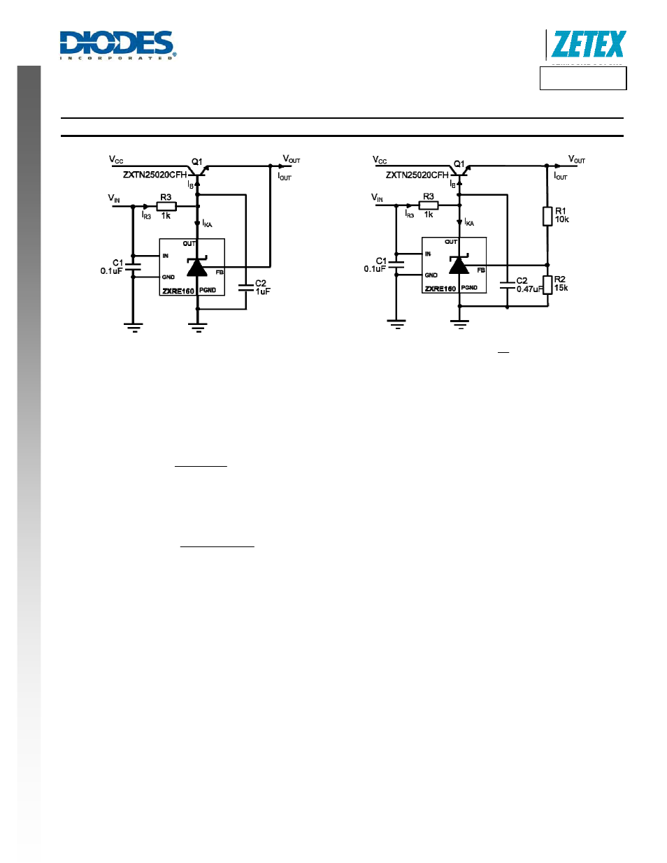
REF
OUT
V
V
=
Figure 6. 0.6V Series LDO Regulator
⎟
⎠
⎞
⎜
⎝
⎛ +
=
2
R
1
R
1
V
V
REF
OUT
Figure 7. 1.0V Series LDO Regulator
Design guide:
1. Determine
I
OUT
and choose a suitable transistor taking power dissipation into consideration.
2. Determine
I
B
from
)
1
h
(
I
I
(min)
FE
(max)
OUT
B
+
=
3. Determine
I
R3
from
(min)
KA
I
B
I
3
R
I
+
≥
. The design of the ZXRE160 effectively means there is no I
KA(min)
limitation as in conventional
references. There is only an output leakage current which is a maximum of 1µA. Nevertheless, it is necessary to determine an I
KA(min)
to
ensure that the device operates within its linear range at all times. I
KA(min)
≥ 10µA should be adequate for this.
4.
Determine R3 from
3
R
BE
OUT
IN
I
)
V
V
(
V
3
R
+
−
=
.
Although unlikely to be a problem, ensure that I
R3
≤ 15 mA.