Zxre160 new prod uc t, Application information – Diodes ZXRE160 User Manual
Page 8
ZXRE160
Document number: DS35688 Rev. 2 - 2
8 of 15
June 2012
© Diodes Incorporated
ZXRE160
NEW PROD
UC
T
A Product Line of
Diodes Incorporated
Application Information
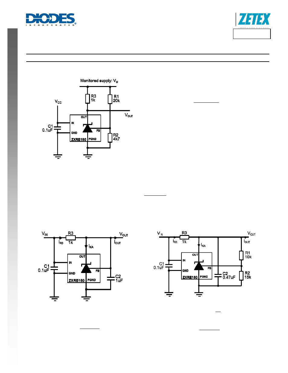
The following show some typical application examples for the ZXRE160.
Figure 3. 15V Supply Monitor
Figure 3 shows a typical configuration for the ZXRE160 in comparator
mode.
Here the comparator switches low when:
(
)
2
2
1
FB
M
R
R
R
V
V
+
≥
Alternative values of R1, R2 may be used to provide different threshold
voltages. R3 can also be adjusted to set the bias current for different
values of V
M
. R2 should be kept as low as possible to minimize errors
due to the bias current of the FB pin.
This circuit has no hysteresis, so a small capacitor of approx.4.7nF
between FB and GND is recommended to provide cleaner transitions at
the output.
In shunt regulator mode it is necessary to include the compensation capacitor C2 to guarantee stability. C2 may range in value from 0.1µF to
10µF depending on the application. The minimum value of C2 can be determined from the following equation (resistor values are in k
Ω):
(
)
μF
R
R
R
R
C2
2
1
3
2
MIN
+
≥
Both C1 and C2 should be as close to the ZXRE160 as possible and connected to it with the shortest possible track. In the case of Figure 10 and
Figure 11, it means the opto-coupler will have to be carefully positioned to enable this.
REF
OUT
V
V
=
3
R
OUT
IN
I
V
V
3
R
−
=
Figure 4. 0.6V Shunt Regulator
⎟
⎠
⎞
⎜
⎝
⎛ +
=
2
R
1
R
1
V
V
REF
OUT
3
R
OUT
IN
I
V
V
3
R
−
=
Figure 5. 1.0V Shunt Regulator