Zxld1360, Absolute maximum ratings, Thermal resistance – Diodes ZXLD1360 User Manual
Page 3: Recommended operating conditions
ZXLD1360
ZXLD1360
Document number: DS33471 Rev. 4 - 2
3 of 25
March 2011
© Diodes Incorporated
A Product Line of
Diodes Incorporated
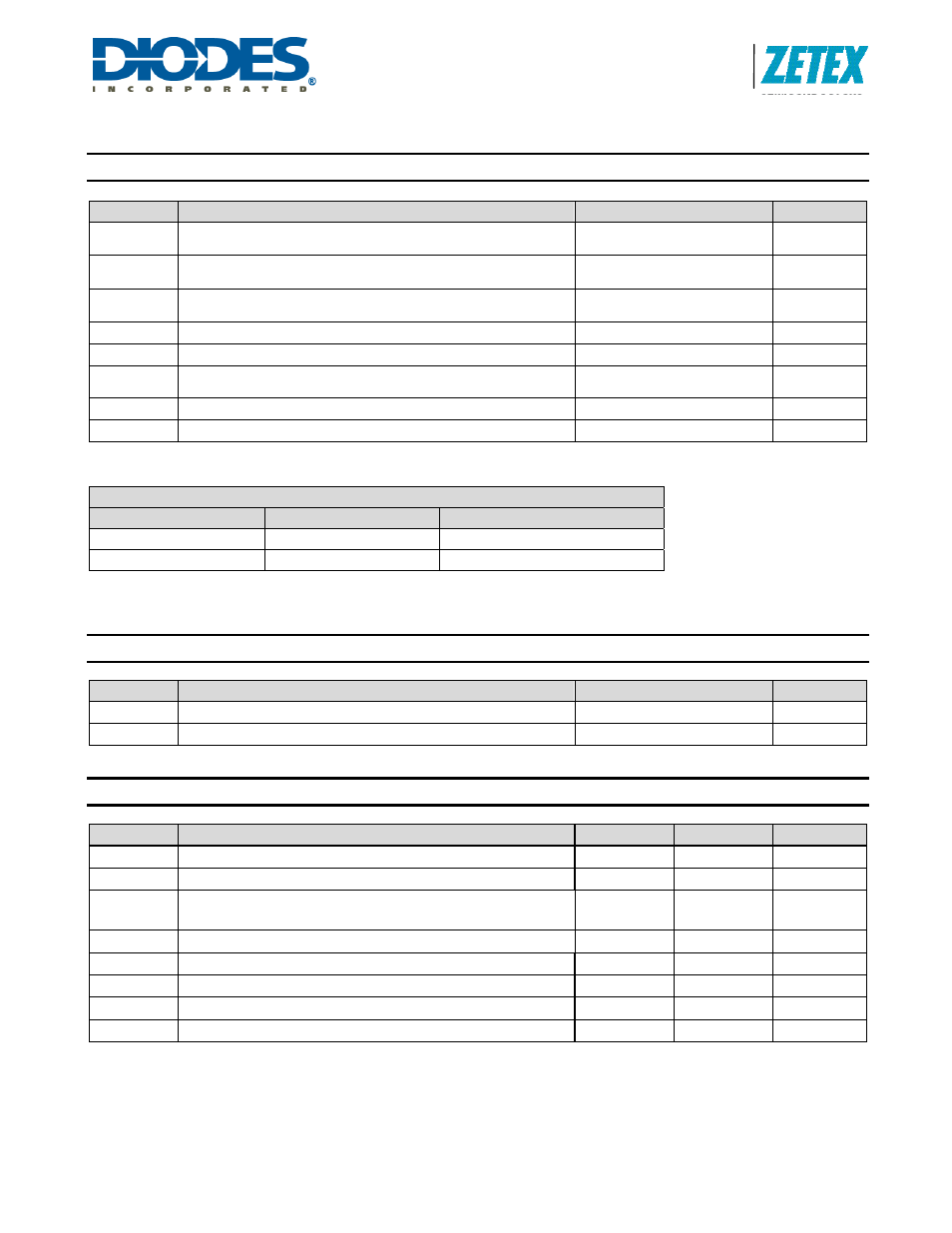
Absolute Maximum Ratings
(Voltages to GND Unless Otherwise Stated)
Symbol
Parameter
Rating
Unit
V
IN
Input Voltage
-0.3 to +30
(40V for 0.5 sec)
V
V
SENSE
I
SENSE
Voltage
+0.3 to -5
(measured with respect to V
IN
)
V
V
LX
LX Output Voltage
-0.3 to +30
(40V for 0.5 sec)
V
V
ADJ
Adjust Pin Input Voltage
-0.3 to +6
V
I
LX
Switch Output Current
1.25
A
P
TOT
Power Dissipation
(Refer to Package thermal de-rating curve on page 20)
1 W
T
ST
Storage Temperature
-55 to 150
°C
T
J
MAX
Junction Temperature
150
°C
These are stress ratings only. Operation above the absolute maximum rating may cause device failure. Operation at the absolute maximum ratings, for extended
periods, may reduce device reliability.
ESD Susceptibility
Rating
Unit
Human Body Model
500
V
Machine Model
<100
V
Semiconductor devices are ESD sensitive and may be damaged by exposure to ESD events. Suitable ESD precautions should be taken when handling and
transporting these devices.
The human body model is a 100pF capacitor discharge through a 1.5k
Ω resistor pin. The machine model is a 200pF capacitor discharged directly into each pin
Thermal Resistance
Symbol
Parameter
Rating
Unit
θ
JA
Junction to Ambient
82
°C/W
Ψ
JB
Junction to Board
33
°C/W
Recommended Operating Conditions
Symbol
Parameter
Min
Max
Units
V
IN
Input Voltage Range
7
30
V
I
LX
Maximum recommended continuous/RMS switch current
1
A
V
ADJ
External control voltage range on ADJ pin for DC brightness
control (Note 2)
0.3 2.5 V
V
ADJoff
DC voltage on ADJ pin to ensure devices is off
0.25
V
t
ONmin
_
REC
Recommended minimum switch “ON” time
800
ns
f
LX max
Recommended maximum operating frequency (Note 1)
625
kHz
D
LX
Duty cycle range
0.01
0.99
T
A
Ambient operating temperature range
-40
125
°C
Notes: 1.
ZXLD1360 will operate at higher frequencies but due to propagation delays accuracy will be affected.
2.100% brightness corresponds to V
ADJ
= V
ADJ(nom)
= V
REF
(~1.25V). Driving the ADJ pin above V
REF
will increase the V
SENSE
threshold and output
current proportionally.