Zxld1360, Application information, Dimming output current using pwm – Diodes ZXLD1360 User Manual
Page 22
ZXLD1360
ZXLD1360
Document number: DS33471 Rev. 4 - 2
22 of 25
March 2011
© Diodes Incorporated
A Product Line of
Diodes Incorporated
Application Information
(cont.)
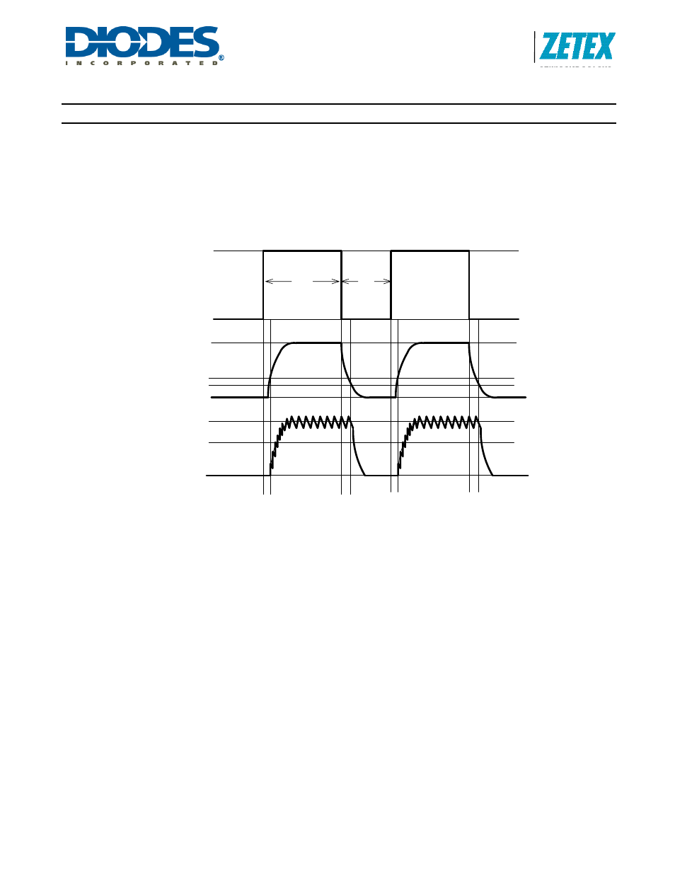
Dimming output current using PWM
Low frequency PWM mode
When the ADJ pin is driven with a low frequency PWM signal (eg 100Hz), with a high level voltage VADJ and a low level of
zero, the output of the internal low pass filter will swing between 0V and V
ADJ
, causing the input to the shutdown circuit to fall
below its turn-off threshold (200mV nom) when the ADJ pin is low. This will cause the output current to be switched on and
off at the PWM frequency, resulting in an average output current I
OUT
avg proportional to the PWM duty cycle.
(See Figure 3 - Low frequency PWM operating waveforms).
Figure 3. Low frequency PWM operating waveforms
The average value of output current in this mode is given by:
I
OUT
avg = 0.1D
PWM
/R
S
[for D
PWM
>0.01]
This mode is preferable if optimum LED 'whiteness' is required. It will also provide the widest possible dimming range
(approx. 100:1) and higher efficiency at the expense of greater output ripple.
Note that the low pass filter introduces a small error in the output duty cycle due to the difference between the start-up and
shut-down times. This time difference is a result of the 200mV shutdown threshold and the rise and fall times at the output of
the filter. To minimize this error, the PWM frequency should be as low as possible consistent with avoiding flicker in the
LED(s).
V
ADJ
V
ADJ
PWM Voltage
Ton
IOUTavg
Filter Output
0V
0V
0
Toff
0.1/Rs
IOUTnom
200mV
300mV
Output Current