Asus P5LD2-X/1333 User Manual
Page 51
ASUS P5LD2-X/1333
2-2
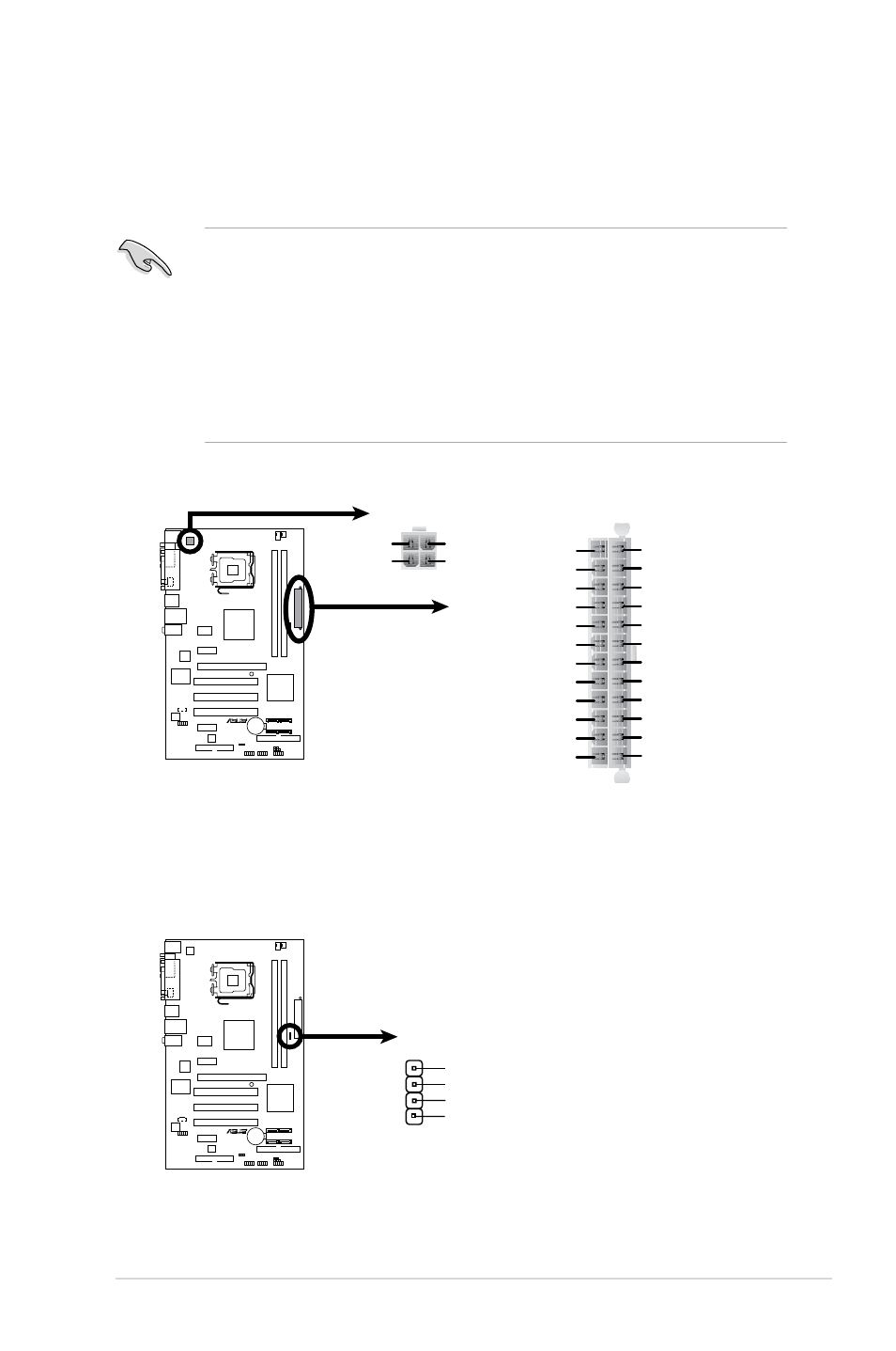
9.. ATX.power.connectors (24-pin EATXPW, 4-pin ATX12V)
These connectors are for ATX power supply plugs. The power supply plugs
are designed to fit these connectors in only one orientation. Find the proper
orientation and push down firmly until the connectors completely fit.
• Use of an ATX 12 V Specification 2.0 -compliant power supply unit (PSU)
that provides a minimum power of 350 W is recommended for a fully-
configured system.
• Do not forget to connect the 4-pin ATX +12 V power plug; otherwise, the
system will not boot up.
• Use of a PSU with a higher power output is recommended when
configuring a system with more power consuming devices. The system may
become unstable or may not boot up if the power is inadequate.
P5LD2-X/1333.ATX.Power.Connector
EATXPWR
+3 Volts
+3 Volts
Ground
+5 Volts
+5 Volts
Ground
Ground
Power OK
+5V Standby
+12 Volts
-5 Volts
+5 Volts
+3 Volts
-12 Volts
Ground
Ground
Ground
PSON#
Ground
+5 Volts
+12 Volts
+3 Volts
+5 Volts
Ground
ATX12V
GND
+12V DC
GND
+12V DC
P5LD2-X/1333
10.. Speaker.connector.(4-pin.SPEAKER)
This 4-pin connector is for the chasis-mounted system warning speaker. The
speaker allows you to hear system beeps and warnings.
P5LD2-X/1333.Speaker.Out.Connector
SPEAKER
+5V
GND
GND
Speaker Out
1
P5LD2-X/1333