P5kpl se ide connector, P5kpl se digital audio connector – Asus P5KPL SE User Manual
Page 31
ASUS P5KPL SE
1-21
4..
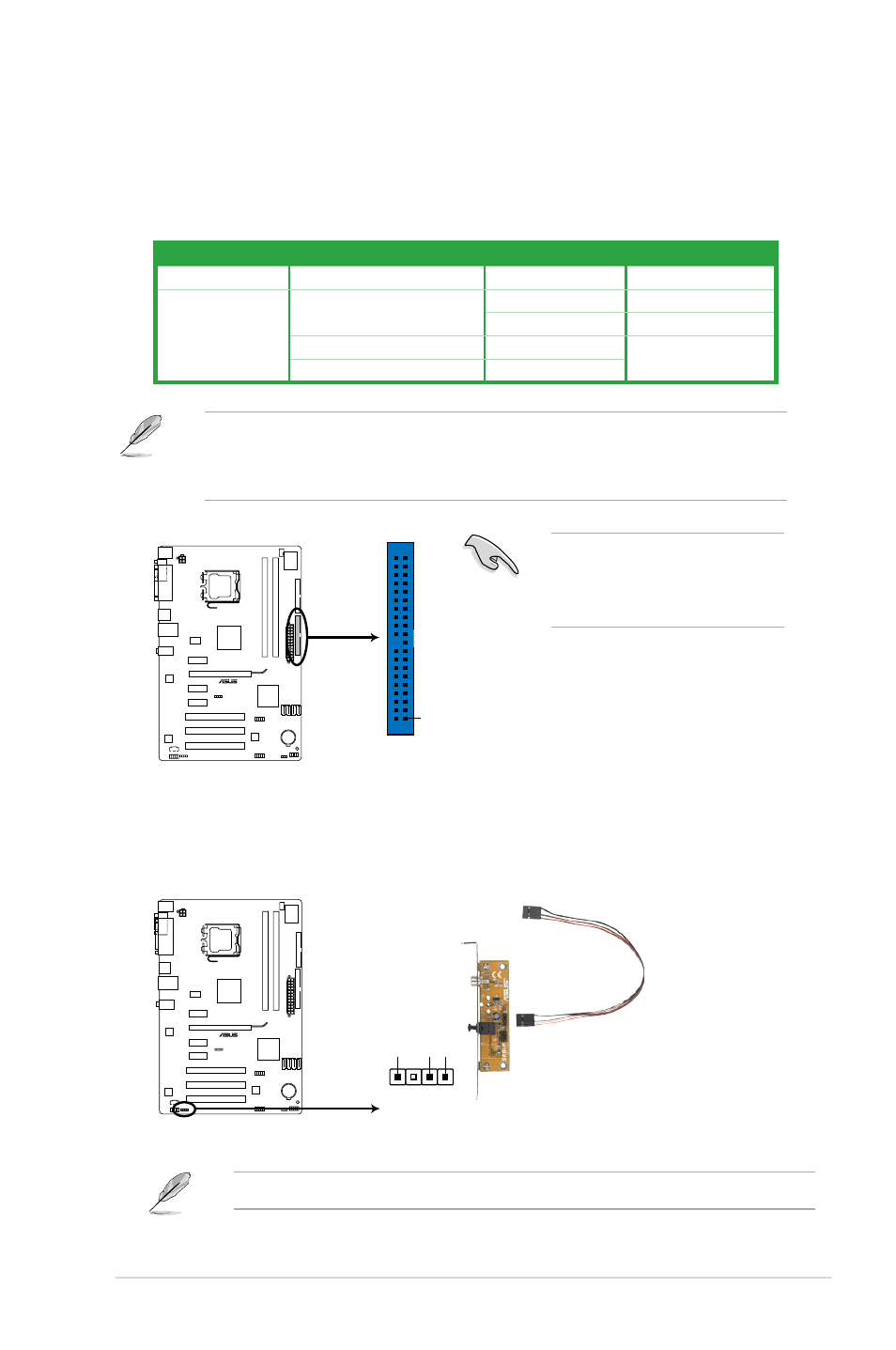
Digital.audio.connector.(4-1.pin.SPDIF_OUT)
This connector is for an additional Sony/Philips Digital Interface (S/PDIF) port. Connect
the S/PDIF Out module cable to this connector, then install the module to a slot
opening at the back of the system chassis.
The S/PDIF module is purchased separately.
3..
IDE.connector.(40-1.pin.PRI_EIDE)
The onboard IDE connector is for the Ultra DMA 100/66/33 signal cable. There are
three connectors on each Ultra DMA 100/66/33 signal cable: blue, black, and gray.
Connect the blue connector to the motherboard’s IDE connector, then select one of the
following modes to configure your device.
Drive.jumper.setting
Mode.of.device(s)
Cable.connector
Single device
Cable-Select or Master
-
Black
Two devices
Cable-Select
Master
Black
Slave
Gray
Master
Master
Black or gray
Slave
Slave
• Pin 20 on the IDE connector is removed to match the covered hole on the Ultra DMA
cable connector. This prevents incorrect insertion when you connect the IDE cable.
• Use the 80-conductor IDE cable for Ultra DMA 100/66/33 IDE devices.
If any device jumper is set as
“Cable-Select,” make sure all other
device jumpers have the same
setting.
P5KPL SE
PRI_IDE
NOTE:Orient the red markings
on the IDE ribbon cable to PIN 1.
PIN1
P5KPL SE IDE connector
P5KPL SE
SPDIF_OUT
+5
V
SPDIFOU
T
GND
P5KPL SE Digital audio connector