28 chapter 2: hardware information, P5nt ws com port connector, Com1 – Asus P5NT WS User Manual
Page 52
2-28
Chapter 2: Hardware information
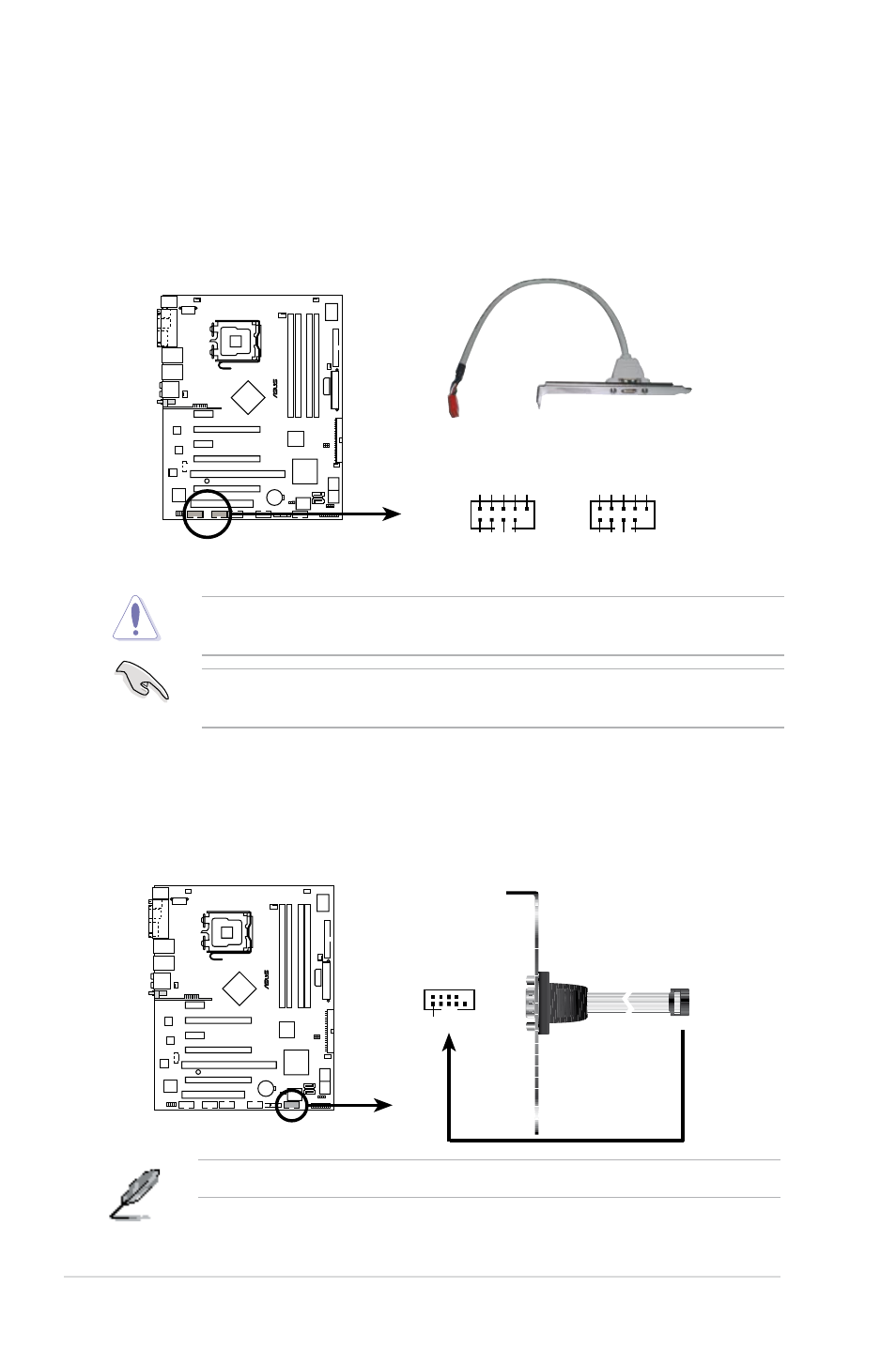
6. IEEE 1394a port connector (10-1 pin IE1394_1; 10-1 pin IE1394_2)
The connectors are for IEEE 1394a ports. Connect the IEEE 1394a module
cable to any of the connectors, then install the module to a slot opening at the
back of the system chassis.
Never connect a USB cable to the IEEE 1394a connector. Doing so will damage
the motherboard!
You can connect the 1394 cable to ASUS Q-Connector (1394, red) first, and
then install the Q-Connector (1394) to the 1394 connector onboard.
P
5
N
T
W
S
®
P5NT WS IEEE 1394 connectors
IE1394_2
PIN1
GN
D
+12V
TPB2
-
GN
D
TP
A2-
+12V
TPB2
+
GN
D
TP
A2+
IE1394_1
PIN1
GN
D
+12V
TPB1
-
GN
D
TP
A1-
+12V
TPB1
+
GN
D
TP
A1+
7. Serial port connector (10-1 pin COM1)
This connector is for a serial (COM) port. Connect the serial port module
cable to this connector, then install the module to a slot opening at the back
of the system chassis.
The Serial (COM) port module is purchased separately.
P
5
N
T
W
S
®
P5NT WS COM port connector
PIN 1
COM1