Asus P5NT WS User Manual
Page 30
2-6
Chapter 2: Hardware information
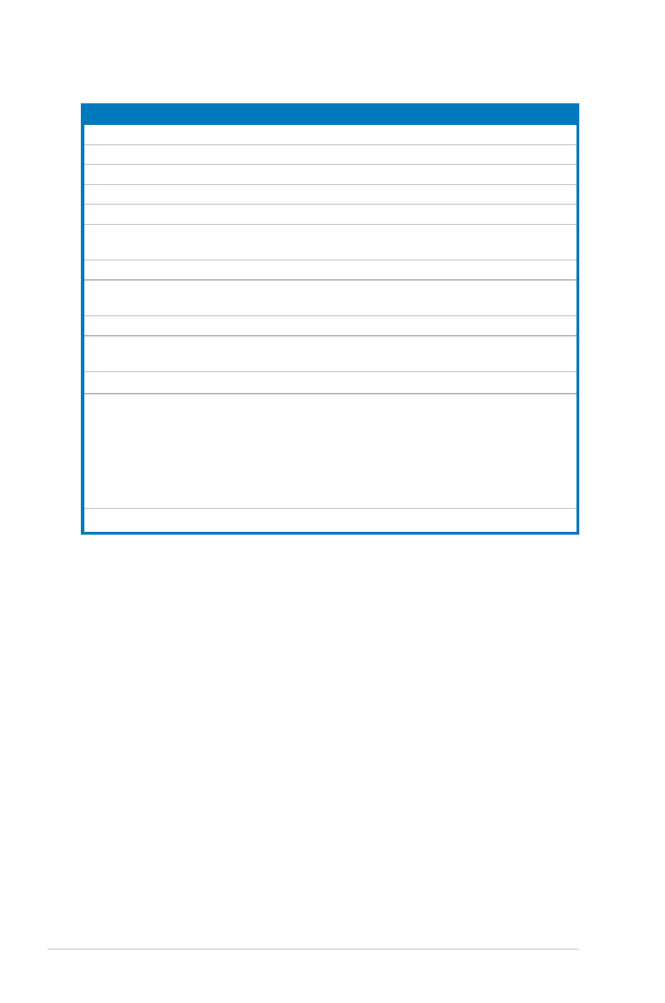
Internal connectors
Page
1.
Floppy disk drive connector (34-1 pin FLOPPY)
2-24
2.
IDE connector (40-1 pin PRI_IDE)
2-25
3.
Serial ATA connectors (7-pin SATA1-6)
2-26
4.
USB connectors (10-1 pin USB56, USB 78, USB910)
2-27
5.
Internal audio connector (4-pin CD)
2-27
6.
IEEE 1394a port connectors (10-1 pin IE1394_1; 10-1 pin
IE1394_2)
2-28
7.
Serial port connector (10-1 pin COM1)
2-28
8.
CPU, chassis, and power fan connectors
(4-pin CPU_FAN, 3-pin CHA_FAN1~4, 3-pin PWR_FAN)
2-29
9.
Chassis intrusion connector (4-1 pin CHASSIS)
2-30
10.
ATX power connectors (24-pin EATXPWR, 2 x 4-pin ATX12V,
4-pin EZ_PLUG)
2-30
11.
TPM connector (20-1 pin TPM)
2-32
12.
System panel connector (20-8-pin PANEL)
• System power LED (2-pin PLED)
• Hard disk drive activity LED (2-pin IDE_LED)
• System warning speaker (4-pin SPEAKER)
• ATX power button/soft-off button (2-pin PWR)
• Reset button (2-pin RESET)
2-33
ASUS Q-connector (system panel)
2-34
- P5B Premium Vista Edition (188 pages)
- P5B (140 pages)
- P5B (56 pages)
- P5KPL-VM/1394/SI (94 pages)
- M2N68-CM (28 pages)
- P5AD2-E Premium (2 pages)
- P5GD1-VM (88 pages)
- P5AD2 Premium (8 pages)
- P5GD1-VM (92 pages)
- DELUXE A7N8X-E (114 pages)
- P5KPL-AM SE (62 pages)
- P5KPL-AM SE (40 pages)
- P5KPL-AM SE (38 pages)
- P4S8X-X (64 pages)
- P5K-VM (98 pages)
- K8V-X SE (82 pages)
- M2N68-AM SE2 (40 pages)
- P4P800 SE (16 pages)
- P4P800 SE (125 pages)
- DELUXE SERIES M3A32-MVP (176 pages)
- P5AD2 Deluxe (148 pages)
- M4A79 Deluxe (122 pages)
- A7V266-E (108 pages)
- Application Manual (4 pages)
- Application Manual (8 pages)
- Application Manual (2 pages)
- Application Manual (6 pages)
- Application Manual (9 pages)
- Application Manual (3 pages)
- Application Manual (1 page)
- Application Manual (5 pages)
- Application Manual (11 pages)
- Application Manual (10 pages)
- M4A88T-I DELUXE (70 pages)
- M4A88T-I DELUXE (44 pages)
- P9X79 DELUXE (2 pages)
- RAMPAGE IV GENE (1 page)
- P9X79 (156 pages)
- P8H61-M PLUS V3 (64 pages)
- A85XM-A (78 pages)
- M4A78L-M LE (64 pages)
- M2N68-AM (96 pages)
- M2N68-AM (62 pages)
- M2N68-AM (38 pages)
- Blitz Formula (2 pages)