P8h61-m evo system panel connector, Panel – Asus P8H61-M EVO User Manual
Page 40
1-28
Chapter 1: Product introduction
11. System panel connector (20-8 pin PANEL)
This connector supports several chassis-mounted functions.
•
System power LED (2-pin PLED)
This 2-pin connector is for the system power LED. Connect the chassis power LED
cable to this connector. The system power LED lights up when you turn on the system
power, and blinks when the system is in sleep mode.
•
Hard disk drive activity LED (2-pin IDE_LED)
This 2-pin connector is for the HDD Activity LED. Connect the HDD Activity LED cable
to this connector. The IDE LED lights up or flashes when data is read from or written to
the HDD.
•
System warning speaker (4-pin SPEAKER)
This 4-pin connector is for the chassis-mounted system warning speaker. The speaker
allows you to hear system beeps and warnings.
•
ATX power button/soft-off button (2-pin PWRSW)
This 2-pin connector is for the system power button.
•
Reset button (2-pin RESET)
This 2-pin connector is for the chassis-mounted reset button for system reboot without
turning off the system power.
P8H61-M EVO
P8H61-M EVO System panel connector
PIN 1
* Requires an ATX power supply
PLED
SPEAKER
PLED
+
PLED
-
+5
V
Groun
d
Groun
d
Speake
r
IDE_LED
+
IDE_LED
-
PWR
Groun
d
Rese
t
Groun
d
PANEL
IDE_LED
PWRSW
RESET
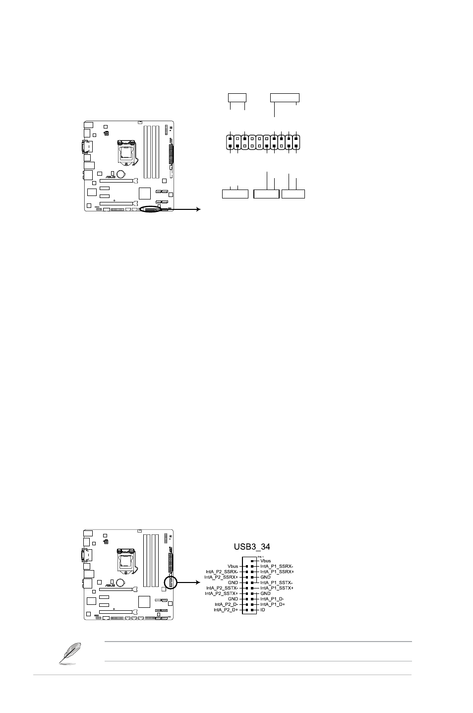
12. USB 3.0 connector (20-1 pin USB3_34)
This connector is for the additional USB 3.0 ports. Connect the USB 3.0 bracket cable
to this connector, then install the USB 3.0 bracket to the rear side of the chassis. If your
chassis support customized front panel installation, with ASUS USB 3.0 header, you
can have a front panel USB 3.0 solution.
P8H61-M EVO
P8H61-M EVO USB3.0 front panel connector
The USB 3.0 module is purchased separately.