Led indicators, Link speed setting – Net Optics 8x1 Regeneration Taps User Manual
Page 8
8x1 Regeneration Taps
5
LED Indicators
• Power LEDs: Each LED illuminates to show that power is being sourced
by one of the power supples.
• Link LEDs: For copper models, a LED on the right corner of each RJ45
illuminates when a link is established. The Link LEDs for fiber network
ports are located in the top two positions in the stack of four LEDs to the
left of the network ports.
• SFP Present LEDs: The left side LED above each SFP/SFP+ cage
illuminates when a module is properly plugged in. The right side LED
about the cage is not used.
• Activity LEDs: For copper models, a LED on the left corner of each RJ45
connector flashes when there is activity on the port.
• Link Speed Indication: For 10/100/1000 copper ports, the color of the
Link LED is amber if the link speed is 10 Mbps, yellow for 100 Mbps, and
green for 1000 Mbps. On the fiber models, bottom two LEDs in the stack of
four LEDs to the left of the network ports indicate whether the model is for
10 Gbps (second-from-bottom LED) or 1 Gbps (bottom LED) link speed.
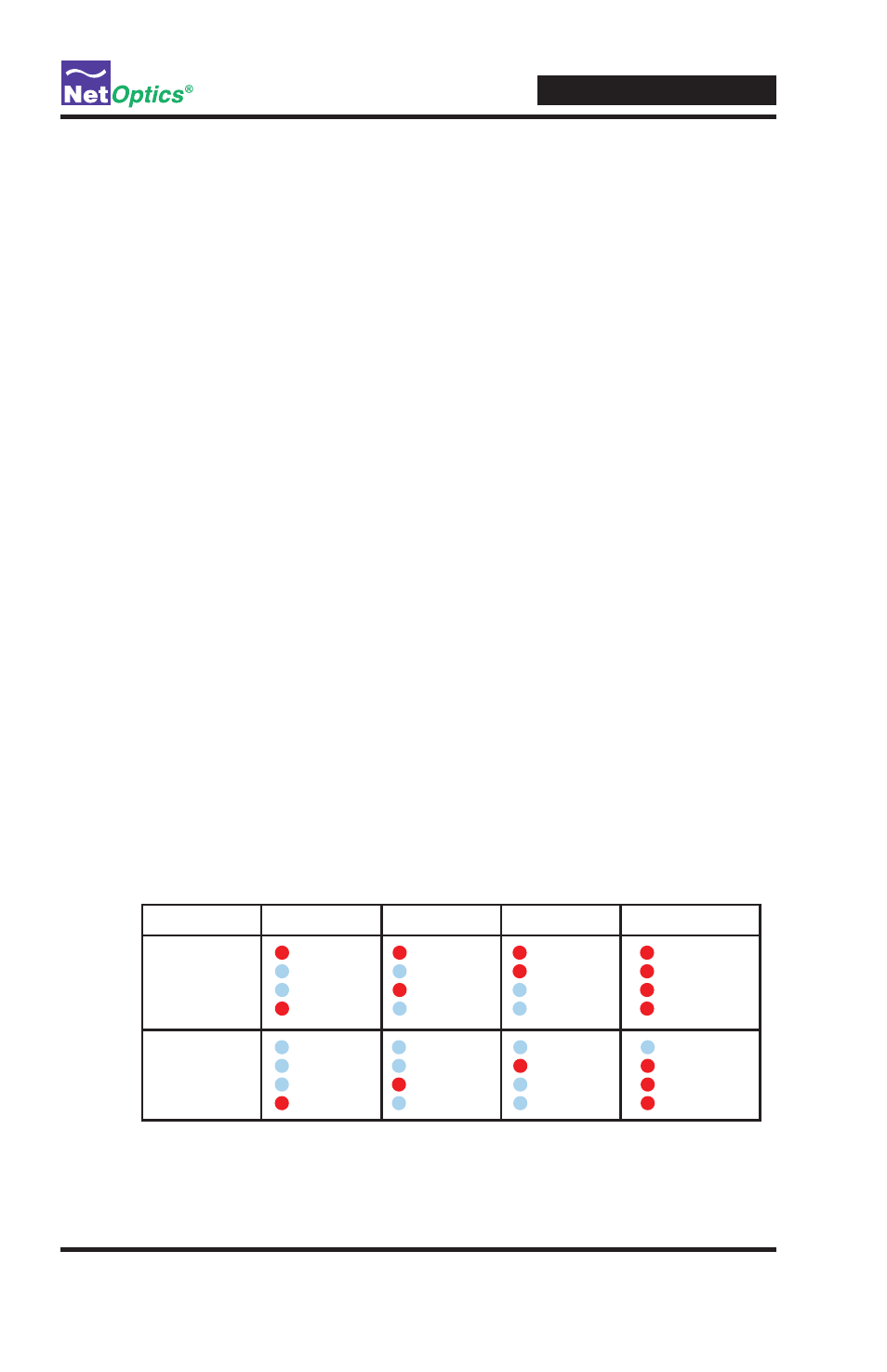
Link Speed Setting
For 10/100/1000 copper interface models, the link speed and duplex mode
are set by pressing the mode change button. The button is recessed to prevent
accidental activation; use a pen tip or straightened paper clip so press it. Each
time you press the button, the mode changes. Press it repeatedly until you
reach your desired operating mode as indicated in the speed and duplex LEDs.
The modes and LED indications are illustrated below.
10 Mbps
100 Mbps
1000 Mbps
Auto-negotiate
Duplex
Full duplex
1000
100
10
Full duplex
1000
100
10
Full duplex
1000
100
10
Full duplex
1000
100
10
Half-duplex
Full duplex
1000
100
10
Full duplex
1000
100
10
Full duplex
1000
100
10
Full duplex
1000
100
10