Q-tech, Qcc325 series, Phase noise and phase jitter integration – Q-Tech QCC325 User Manual
Page 4
44
Q-TECH Corporation - 10150 W. Jefferson Boulevard, Culver City 90232 - Tel: 310-836-7900 - Fax: 310-836-2157 - www.q-tech.com
QCC325 SERIES
LOW PROFILE 5 x 3.2mm MINIATURE SMD CRYSTAL OSCILLATORS
1.8 to 5.0Vdc - 1MHz to 220.000MHz
QCC325 (Revision F, August 2010) (ECO# 9911)
Q-TECH
CORPORATION
Phase noise is measured in the frequency domain, and is expressed as a ratio of signal power to noise power measured in a 1Hz
bandwidth at an offset frequency from the carrier, e.g. 10Hz, 100Hz, 1kHz, 10kHz, 100kHz, etc. Phase noise measurement is made
with an Agilent E5052A Signal Source Analyzer (SSA) with built-in outstanding low-noise DC power supply source. The DC source
is floated from the ground and isolated from external noise to ensure accuracy and repeatability.
In order to determine the total noise power over a certain frequency range (bandwidth), the time domain must be analyzed in the
frequency domain, and then reconstructed in the time domain into an rms value with the unwanted frequencies excluded. This may be
done by converting L(f) back to Sφ(f) over the bandwidth of interest, integrating and performing some calculations.
The value of RMS jitter over the bandwidth of interest, e.g. 10kHz to 20MHz, 10Hz to 20MHz, represents 1 standard deviation of
phase jitter contributed by the noise in that defined bandwidth.
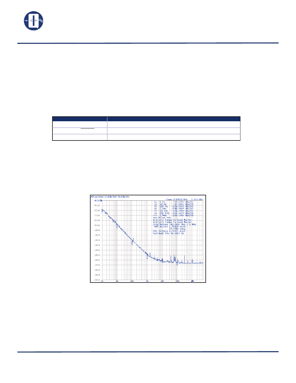
Figure below shows a typical Phase Noise/Phase jitter of a QCC325, 3.3Vdc, 25MHz clock at offset frequencies 1Hz to 1MHz, and
phase jitter integrated over the bandwidth of 12kHz to 1MHz.
Phase Noise and Phase Jitter Integration
Symbol
Definition
∫
L(f)
Integrated single side band phase noise (dBc)
Sφ (f)=(180/Π)x
√
2 ∫
L(f)df
Spectral density of phase modulation, also known as RMS phase error (in degrees)
RMS jitter = Sφ (f)/(fosc.360°)
Jitter(in seconds) due to phase noise. Note Sφ (f) in degrees.