Halotronic, Intelligent dali, Sample touchdim – OSRAM HALOTRONIC Electronic transformers HTi User Manual
Page 2: Wiring diagram, Sample dali, Wiring diagram 6. sample sensor & touchdim, Wiring (multieco)
HALOTRONIC INT DALI 105 A#32846 05.01.2010 13:20 Uhr Seite 2
C
M
Y
CM
MY
CY CMY
K
G
1
029243
1
C1
0238698
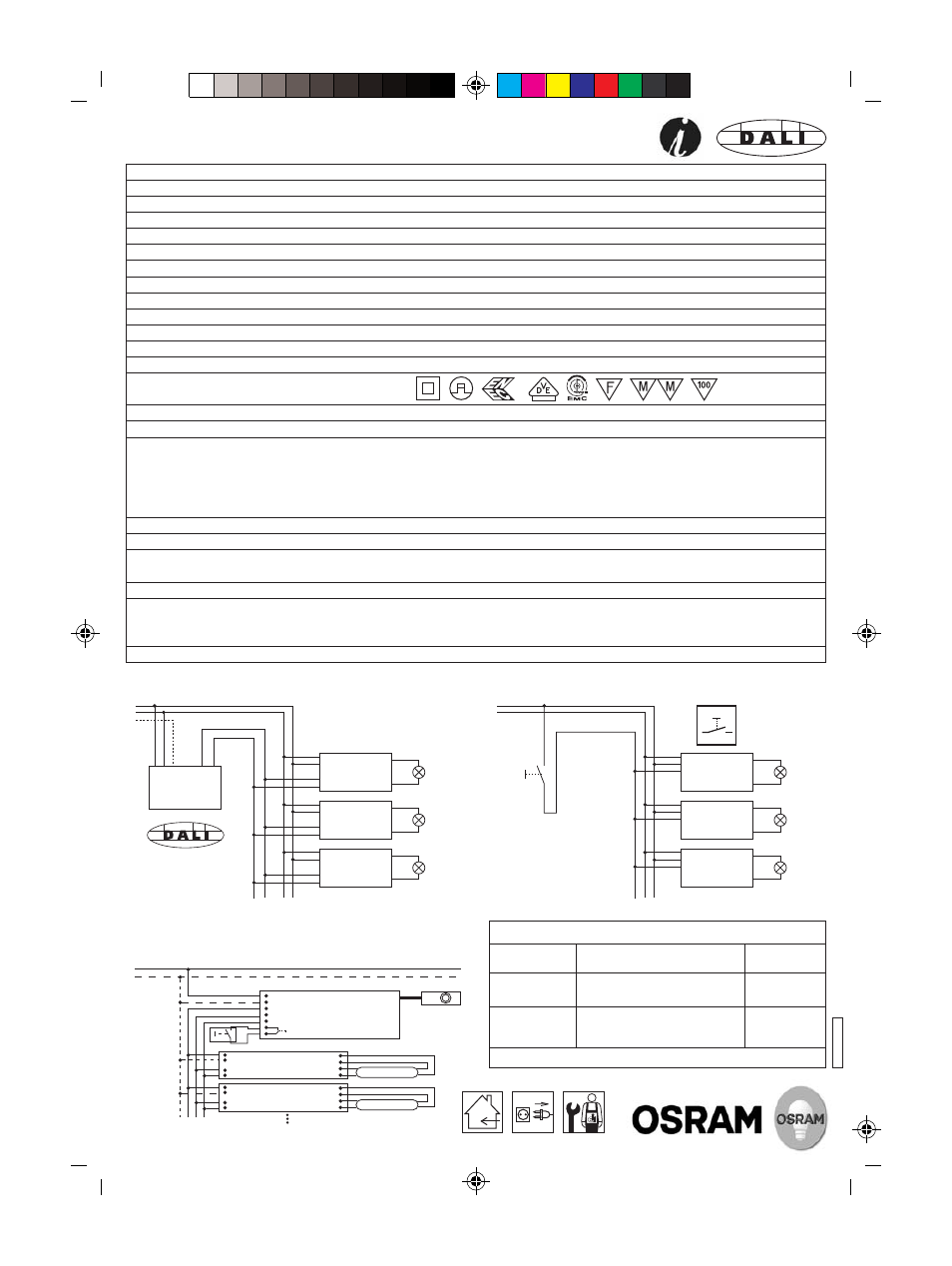
5. Sample TouchDIM
®
wiring diagram
HALOTRONIC
®
INTELLIGENT DALI
®
Reference:
HTi DALI 105/230-240 DIM
Nominal line voltage:
230 V - 240 V
Voltage range (AC):
207 V - 254 V
Safe operation:
207 V - 264 V
AC
; 176 V - 275 V
DC
Range of battery voltage for emergency installation:
176 V - 275 V
Nominal line current:
≤ 0.45 A
eff.
Line frequency:
0; 50 - 60 Hz
Power factor:
≥ 0.95
Output voltage (@ 240 V):
11.5 V (35 W); 11.8 V (105 W)
Losses:
≤ 6 W (@ 105 W)
Stand-by/No-load input power
< 0.5 W
Load range:
35 - 105 W
Standards:
EN 55015 (A1: 2007); EN 61000-3-2; EN 61547; EN 61347-2-2
Approvals:
Temperature range:
-20 °C to +50 °C
Max. inrush current for cold lamps @ 150 W:
< 0.6 A
Dimming interface:
DALI
®
or TouchDIM
®
(1-switch-dimm-function) with separated
and not isolated TouchDIM
®
input (TDi)
TouchDIM
®
Sensor functions are also integrated.
DALI
®
interface is protected against polarity reversal and
over-voltage (max. 500 V, basic isolation, no SELV)
Dimming range:
0.1 - 100% luminous flux with AC; 1 - 100% with DC
Protection against short circuit, overload and overheating:
Automat. switch off, reversible
Suitable cable types for primary side:
H03VV-F2x0.50mm
2
; H03VV-F2x0.75mm
2
; H05VVH2-F2X0.75mm
2
;
H03VVH2-F2x0.75mm
2
; NYM-O 2x1.5 mm
2
;
NYM-J 3x1.5 mm
2
Wire cross section, primary:
0.5 mm
2
to 1.5 mm
2
Suitable cable types for secondary side:
H05VVH2-F2x0.75mm
2
; H05VV-F2x1.5mm
2
; H05VV-F2x2.5mm
2
;
H03VV-F2x0.75mm
2
; NYM-J 3x1.5 mm
2
; NYM-J 3x2.5 mm
2
;
NYM-O 2x1.5 mm
2
Wire cross section, secondary:
0.75 mm
2
to 2.5 mm
2
10
TOUCH
DIM
L
N
L
N
Push
button
T
DA
HTi DALI
105
~
~
DA
12V
(35-105W)
TDi
DA
~
~
DA
12V
(35-105W)
TDi
DA
~
~
DA
12V
(35-105W)
TDi
HTi DALI
105
HTi DALI
105
L
N
PE
L
N
L N PE
DA
DA
DA
DA
DA
~
~
DA
12V
(35-105W)
DA
~
~
DA
12V
(35-105W)
DA
~
~
DA
12V
(35-105W)
DALI
Control Unit
HTi DALI
105
HTi DALI
105
HTi DALI
105
4. Sample DALI
®
wiring diagram
6. Sample Sensor & TouchDIM
®
wiring
(MULTIeco)
Recommended energy saving accessories (not included)
DALI MULTIeco
DALI
®
control unit for use of
LS/PD MULTI 3 sensors
4008321371300
LS/PD MULTI 3 CI
Light- and presence sensor for ceiling
integration
4008321916648
ECO CI KIT
Cable clamp for independent
mounting of the DALI MULTIeco
control unit (e.g. ceiling integration)
4008321392091
www.osram.com/ecg-lms
OSRAM GmbH, Steinerne Furt 62, 86167 Augsburg, Germany
L
N
L
N
L'
DA+
DA-
Sensor
DALI MULTIeco
~
DA
DA
~
HTi DALI 105
Push button
Lamp
~
DA
DA
~
HTi DALI 105
Lamp
www.osram.com