Axial lead & cartridge fuses, 5×20 mm > time-lag (slo-blo, 215sp series – Littelfuse 215SP Series User Manual
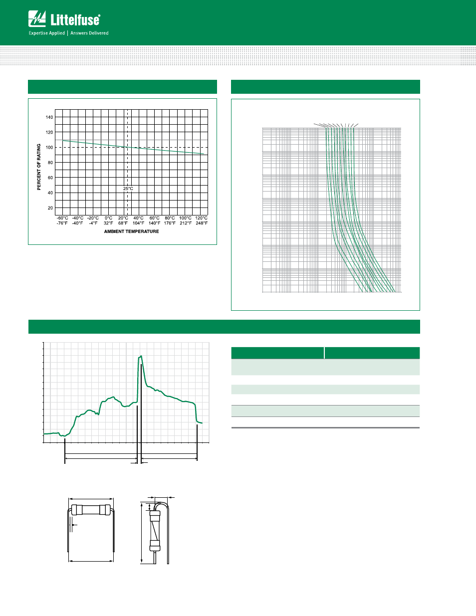
Page 2: Average time current curves
© 2013 Littelfuse, Inc.
Specifications are subject to change without notice.
Revised: 12/19/13
Axial Lead & Cartridge Fuses
5×20 mm > Time-Lag (Slo-Blo
®
) > 215SP Series
Average Time Current Curves
215001.
2151.25 21501.6 215002. 21502.5 2153.15 215004. 215005. 21506.3.
215010.
215008.
0.001
0.01
0.1
1
10
100
1000
10000
0.01
0.1
1
10
100
Time (seconds)
Amps
Temperature Rerating Curve
Soldering Parameters - Wave Soldering
Dwell Time
0
20
40
60
80
100
120
140
160
180
200
220
240
260
280
300
0
10
20
30
40
50
60
70
80
90
100
110
120
130
140
150
160
170
180
190
200
210
220
230
240
Time (Seconds)
Temperature (°C) - Measured on bottom side of board
Cooling Time
Preheat Time
Wave parameter
lead-Free Recommendation
preheat:
(Depends on Flux Activation Temperature)
(Typical Industry Recommendation)
Temperature Minimum:
100
°
C
Temperature Maximum:
150
°
C
Preheat Time:
60-180 seconds
Solder pot Temperature:
260
°
C Maximum
Solder Dwell Time:
2-5 seconds
Recommended Hand-Solder Parameters:
Solder Iron Temperature: 350° C +/- 5°C
Heating Time: 5 seconds max.
Note: These devices are not recommended for IR or
Convection Reflow process.
Recommended Process Parameters:
For the pigtailed fuse, please follow the recommendations
below for axial lead forming and mounting into PCB:
Lead forming:
The distance C between cap flat surface and axial lead shall
be greater than 1.0 mm.
PCB mounting:
The distance between PCB and fuse cap is recommended to
be a minimum of 1.5 mm.
A
B
C
C
A
B
Different values of A and B available, please contact the Littelfuse sales representative in your region: