Sidactor, Protection thyristors, Baseband protection (voice-ds1) – Littelfuse SIDACtor Balanced Multiport Series MS-013 User Manual
Page 4: 25°c
SIDACtor
®
Protection Thyristors
156
Revised: February 22, 2011
© 2011 Littelfuse, Inc.
Specifications are subject to change without notice.
Please refer to www.littelfuse.com for current information.
Baseband Protection (Voice-DS1)
I
H
I
T
I
S
I
DRM
V
DRM
V
T
+V
-V
+I
-I
V
S
50
100
0
t
r
t
d
0
Peak
Value
Half Value
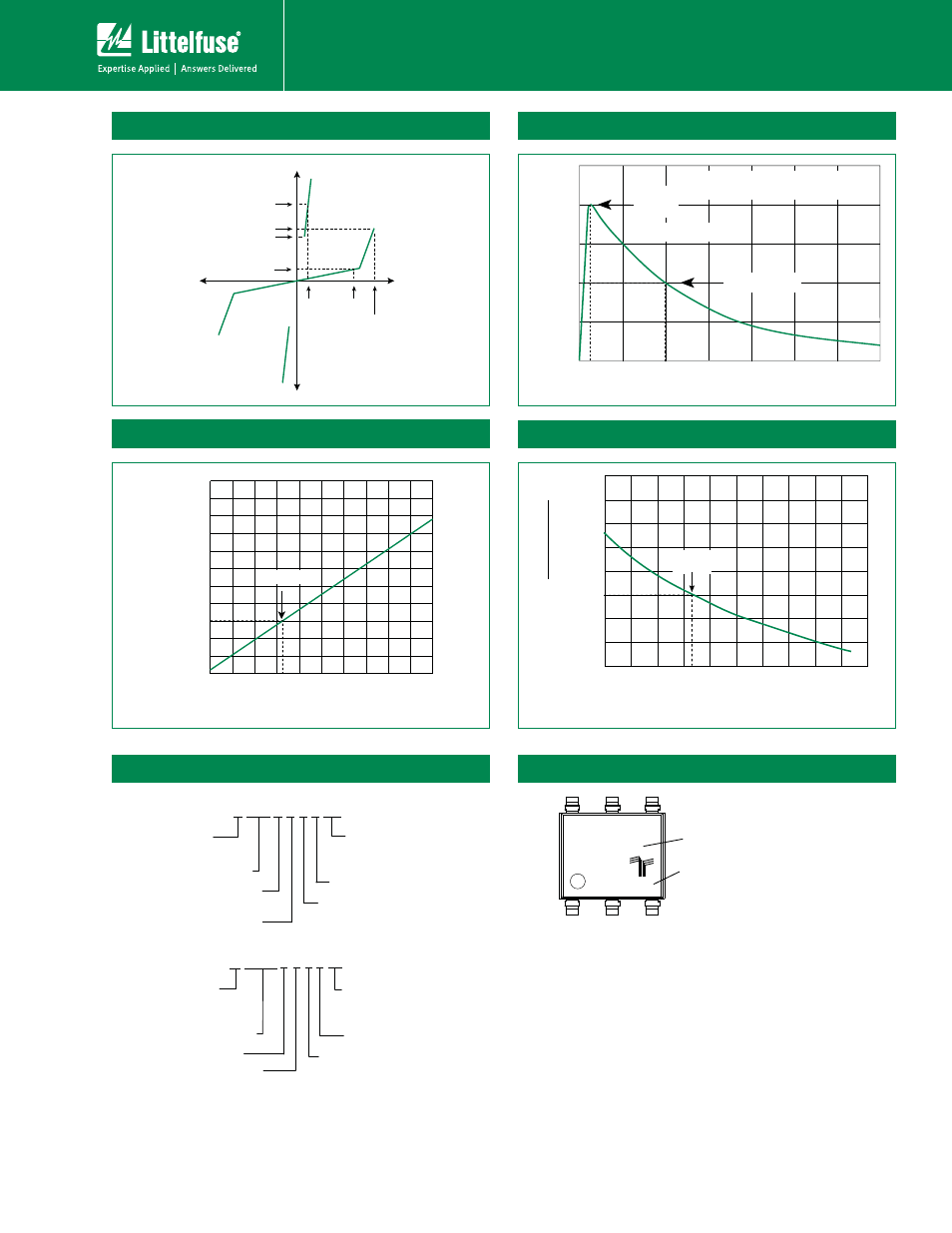
t – Time (μs)
I
PP
– P
eak Pulse Current – %I
PP
t
r
= rise time to peak value
t
d
= decay time to half value
Waveform = t
r
x t
d
V-I Characteristics
t
r
x t
d
Pulse Waveform
25°C
Case Temperature (T
C
) - ºC
2.0
1.8
1.6
1.4
1.2
1.0
0.8
0.6
0.4
-40
-20
0
20
40
60
80
100 120 140 160
R
atio of
I
H
I
H
(T
C
= 25ºC)
Normalized V
S
Change vs. Junction Temperature
Normalized DC Holding Current vs. Case Temperature
Part Numbering
A xxxxU x 6 L xx
TYPE
MEDIAN VOLTAGE
PACKAGE TYPE
I
PP
RATING
RoHS COMPLIANT
CONSTRUCTION VARIABLE
PACKING OPTIONS
RP: Reel Pack
TP: Tube Pack
A: Asymmetrical
SIDACtor
P xxx 6 U x L xx
TYPE
P: SIDACtor
MEDIAN VOLTAGE
CONSTRUCTION
VARIABLE
PACKAGE TYPE
I
PP
RATING
RoHS COMPLIANT
PACKING OPTIONS
RP: Reel Pack
TP: Tube Pack
Part Marking
XXXXXXX
XXXXX
Part Marking Code
(Refer to Electrical Characteristics Table)
Date Code
-8
-40 -20
0
20 40 60 80 100 120 140 160
-6
-4
0
2
4
6
8
10
12
14
Junction Temperature (T
J
) – °C
P
ercent of
V
S
Change – %
25 °C