Protection relays & controls, Wiring diagram, Specifications – Littelfuse SE-330_HV Series User Manual
Page 2: Neutral-grounding-resistor monitoring, Features & benefits, Typical values, Neutral-grounding-resistor monitor
Protection Relays & Controls
© 2013 Littelfuse Protection Relays & Controls
CONTROL
POWER
UNIT
HEALTHY
PULSE
ENABLE
RESET
TRIP OR
PULSING
RESISTOR
FAULT
GROUND
FAULT
+
POWER SYSTEM
NEUTRAL (X0)
R
EFCT
1 A
5 A
COMMON
G
ANALOG
OUTPUT
4-20 mA
+24 Vdc
0 V
(required)
(required)
NEUTRAL-GROUNDING-
RESISTOR MONITOR
SE-330 SERIES
ER SERIES
EFCT FAMILY
SENSING RESISTOR
CURRENT TRANSFORMER
29
28
27
26
11
10
9
8
3
2
1
25
24
23
17
16
15
13
12
22
21
20
19
18
7
6
R
G
N
A
B
Specifications
IEEE Device Numbers
Ground Fault (50G/N, 51G/N, 59N),
Checking Relay (3), Lockout Relay (86)
Input Voltage
See ordering information
Dimensions H
213 mm (8.4"); W 98 mm (3.9"); D 132 mm (5.2")
GF Trip-Level Settings
2-100% of CT-Primary Rating
GF Trip-Time Settings
0.1-10 s
Vn Trip-Level Settings
20-2,000 Vac (≤5 kV systems)
100-10,000 Vac (>5 kV systems)
Contact Operating Mode Selectable fail-safe or non-fail-safe (K1)
Harmonic Filtering
Standard feature
Reset Button
Standard feature
Output Contacts
Two Form A and two Form C
Pulsing Circuit
1.0-3.0 s in 0.2 s increments
Approvals
CSA certified, UL Listed (E340889),
CE (European Union) optional, C-Tick (Australian)
Communications
RS-232; (standard) DeviceNet
™
, Profibus
®
,
Ethernet (optional)
Analog Output
4-20 mA, self or loop powered
Conformally Coated
Standard feature
Warranty
5 years
Mounting
Panel and Surface
Neutral-Grounding-Resistor Monitoring
FEATuRES
iEEE #
bENEFiTS
Continuous NGR monitoring
3
Detects resistor failure within seconds, reduces transient-overvoltage risk, removes risk of ground-fault-detection failure
Ground-fault detection
50G/N, 51G/N,
59N
Main or backup protection to detect a ground fault anywhere on the monitored system
Adjustable pickup (2-100%)
Select greatest sensitivity without false operation
Adjustable time delay (0.1 - 10 s)
Adjustable trip delay allows quick protection and system coordination
Universal CT compatibility
Allows the use of a CT that gives required ground-fault settings
Output contacts
Two Form C (Ground Fault and Resistor Fault), Two Form A (Trip/Pulse, Healthy)
Analog output (4 - 20 mA)
Allows for connecting an optional PGA-0500 meter or control system
Pulsing output
Control the operation of a pulsing ground-fault-location circuit
Data logging
On-board 10-event recorder helps with system diagnostics
Harmonic filtering (DFT)
Eliminate false trips due to harmonic noise from ASDs
Local communications
RS-232 port to view measured values, log to a PC and check event records
Network communications
Remotely view measured values and event records, reset trips, and cause a remote trip
Software
PC-interface software (SE-MON330) is included
Selectable contact
operating mode
Selectable fail-safe or non-fail-safe operating modes allows connection to shunt or undervoltage breaker coil
or alarm circuit
Selectable reset mode
Selectable latching or auto-reset operation
Calibrate push button
Ensures resistor-failure sensitivity is correct
Unit-healthy output
Verifies SE-330 is operating correctly
Conformal coating
Internal circuits are conformally coated to protect against corrosion and moisture
Features & Benefits
SYSTEM
VOLTAGE
(VOLTS)
NEuTRAL-GROuNdiNG RESiSTOR
SENSiNG RESiSTOR
GROuNd-FAuLT
PiCKuP LEVEL
(AMPERES)
V
N
PiCKuP LEVEL
(VOLTS)
CuRRENT
(AMPERES)
RESiSTANCE
(OHMS)
MOdEL
RESiSTANCE
(SWiTCH S5 SETTiNG)
480
5
55
ER-600VC
20 kΩ
2.5
170
600
5
69
ER-600VC
20 kΩ
2.5
200
2,400
5
277
ER-5KV
20 kΩ
2.5
800
4,160
5
480
ER-5KV
20 kΩ
3
1,700
7,200
10
416
ER-15KV
100 kΩ
2
170 x 5 = 850
14,400
15
554
ER-15KV
100 kΩ
3
340 x 5 = 1,700
Typical Values
diSCLAiMER: The above table is for illustrative purposes only. Actual values may differ based on a variety of individual system considerations, such as capacitive charging current and coordination study results.
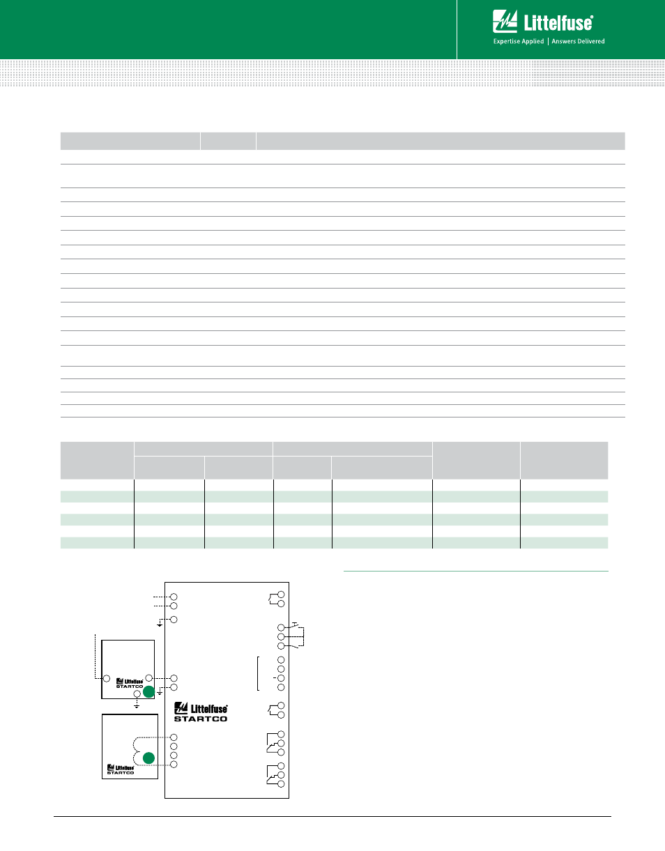
Wiring Diagram
SE-330, SE-330HV SERiES (PGR-5330)
Neutral-Grounding-Resistor Monitor
Rev: 4-B-050213
Based on Manual Rev 9
Littelfuse reserves the right to make product changes, without notice. Material in this document is as accurate as known at the time of publication. Visit Littelfuse.com for the most up-to-date information.
© 2013 Littelfuse Protection Relays & Controls
Littelfuse.com/se-330