Tvs diode arrays, Lightning surge protection - sp3050 series, Family of products) – Littelfuse SP3050 Series User Manual
Page 3: Sp3050, Pulse waveform capacitance vs. reverse bias, Soldering parameters ordering information, Part numbering system part marking system
131
©2011 Littelfuse, Inc.
Specifications are subject to change without notice.
Please refer to
www.littelfuse.com/SPA
for current information.
TVS Diode Arrays
(SPA
™
Family of Products)
Revision: June 27, 2011
SP3050 Series
SP3050
Lightning Surge Protection - SP3050 Series
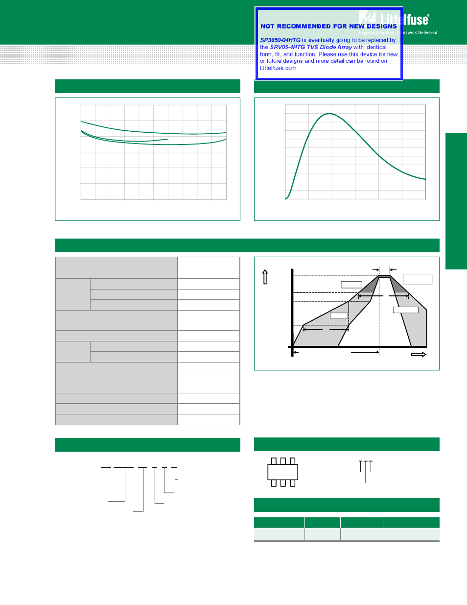
Pulse Waveform
Capacitance vs. Reverse Bias
0.0
0.5
1.0
1.5
2.0
2.5
3.0
0.0 0.5 1.0 1.5 2.0 2.5 3.0 3.5 4.0 4.5 5.0
DC Bias (V)
Capacitance (pF)
V
CC
=Float
V
CC
=5V
V
CC
=3.3V
0%
10%
20%
30%
40%
50%
60%
70%
80%
90%
100%
110%
0.0 5.0 10.0 15.0 20.0 25.0 30.0
Time (μs)
Percent of
I
PP
Time
T
emperature
T
P
T
L
T
S(max)
T
S(min)
25
t
P
t
L
t
S
time to peak temperature
Preheat
Preheat
Ramp-up
Ramp-up
Ramp-down
Ramp-do
Critical Zone
T
L
to T
P
Critical Zone
T
L
to T
P
Reflow Condition
Pb – Free assembly
Pre Heat
- Temperature Min (T
s(min)
)
150°C
- Temperature Max (T
s(max)
)
200°C
- Time (min to max) (t
s
)
60 – 180 secs
Average ramp up rate (Liquidus) Temp
(T
L
) to peak
3°C/second max
T
S(max)
to T
L
- Ramp-up Rate
3°C/second max
Reflow
- Temperature (T
L
) (Liquidus)
217°C
- Temperature (t
L
)
60 – 150 seconds
Peak Temperature (T
P
)
260
+0/-5
°C
Time within 5°C of actual peak
Temperature (t
p
)
20 – 40 seconds
Ramp-down Rate
6°C/second max
Time 25°C to peak Temperature (T
P
)
8 minutes Max.
Do not exceed
260°C
Soldering Parameters
Ordering Information
Part Number
Package
Marking
Min. Order Qty.
SP3050-04HTG
SOT23-6
L*4
3000
Part Numbering System
Part Marking System
SP 3050 04 H T G
Series
Number of
Channels
Package
H: SOT23-6
T= Tape & Reel
G= Green
–
Silicon Protection
Array (SPA
TM
)
Family of
TVS Diode Arrays
L*4
L * 4
Product Series
L = SP3050
Number of Channels
Assembly Site
(Varies)
L = SP3050
(Varies)