Teccor, Brand thyristors, Standard bidirectional diac trigger – Littelfuse STxxx Series User Manual
Page 3: Dia cs, Figure 4: normalized v, Change vs. junction temperature
339
©2008 Littelfuse, Inc.
Revised: July 9, 2008
Teccor
®
brand Thyristors
Specifications are subject to change without notice.
Please refer to http://www.littelfuse.com for current information.
339
©2008 Littelfuse, Inc.
Teccor
®
brand Thyristors
Specifications are subject to change without notice.
Please refer to http://www.littelfuse.com for current information.
HTxxx & HTMxxx & STxxx Series
Standard Bidirectional DIAC Trigger
DIA
Cs
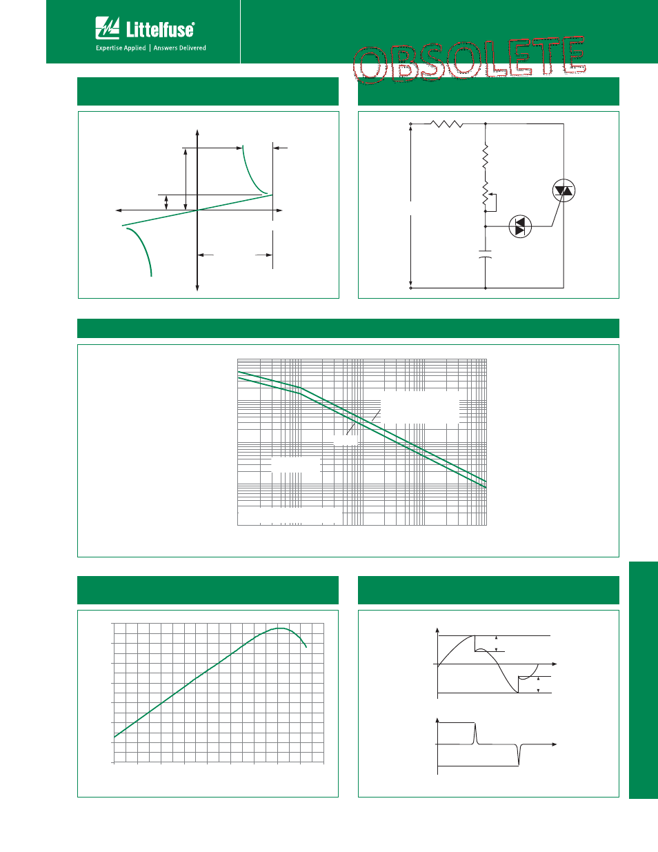
Figure 1: V-I Characteristics
Figure 2: Typical DIAC/Triac Full-wave Phase Control
Circuit
120 V ac
60 Hz
Resistive Load
3.3 k
200 k
0.1 μF
100 V
Diac
Triac
MT2
MT1
G
Figure 3: Repetitive Peak On-state Current vs. Pulse Duration
1
2
4
0
0
0
0
1
0
0
0
4
0
0
0
2
0
0
0
1
0
0
4
0
0
2
6
.001
.002
.003
.005
0.1
0.2
0.3
3.0
0.5
5.0
.01
0.02
0.03
0.05
1.0
10
2.0
Repetitive Peak On-state Current (I
TRM
) – Amps
Base Pulse Duration – μs
Safe Operating
Area
10
20
40 60 100
PULSE REPETITION RATE = 120 pps
T
A
= 40 ˚C
HT-60
HTM-32B
HT-32x, -34x, -35, -36x, -40
HT-5761, -5761A, -5762
ST-32x, -34x, -35, -36x, -40
Figure 4: Normalized V
BO
Change
vs. Junction Temperature
-8%
-6%
-4%
-2%
0%
2%
4%
6%
-40
-20
0
20
40
60
80
100
120
140
Junction Temperature (T
J
) -- °C
V
BO
C
h
a
nge
-
- %
Figure 5: Test Circuit Waveforms
(Refer to Figure 5)